A protected surface mining or hoist rope for an electric dipper shovel is provided. The protected surface mining or hoist rope can include a base rope portion and one or more armoring shield segments applied to the base rope portion. The armoring shield segments can be spaced apart along the length of the protected surface mining or hoist rope to provide additional protection at high-impact or abrasion areas of the rope.
An electromechanical cable that has fluid/gas migration protection is provided as well as a method for manufacturing a fluid/gas migration protected electromechanical cable. The cable can include a core having at least one conductor or fiber optic, a first jacket layer surrounding the core, a sealing layer surrounding the first jacket layer, and a first armor layer surrounding the sealing layer. In one embodiment, the sealing layer can be applied to the cable in a viscous material state and may be a two-part epoxy or synthetic filler material to form a seal between one or more spaces between the armor wire layer and the first jacket layer. In one embodiment, the sealing layer can be applied to the cable in a solid material state and may be a thermoplastic elastomer or silicone-based material or a combination of both.
An electromechanical cable that has fluid/gas migration protection is provided as well as a method for manufacturing a fluid/gas migration protected electromechanical cable. The cable can include a core having at least one conductor or fiber optic, a first jacket layer surrounding the core, a sealing layer surrounding the first jacket layer, and a first armor layer surrounding the sealing layer. In one embodiment, the sealing layer can be applied to the cable in a viscous material state and may be a two-part epoxy or synthetic filler material to form a seal between one or more spaces between the armor wire layer and the first jacket layer. In one embodiment, the sealing layer can be applied to the cable in a solid material state and may be a thermoplastic elastomer or silicone-based material or a combination of both.
H01B 3/28 - Insulators or insulating bodies characterised by the insulating materialsSelection of materials for their insulating or dielectric properties mainly consisting of organic substances natural or synthetic rubbers
H01B 3/30 - Insulators or insulating bodies characterised by the insulating materialsSelection of materials for their insulating or dielectric properties mainly consisting of organic substances plasticsInsulators or insulating bodies characterised by the insulating materialsSelection of materials for their insulating or dielectric properties mainly consisting of organic substances resinsInsulators or insulating bodies characterised by the insulating materialsSelection of materials for their insulating or dielectric properties mainly consisting of organic substances waxes
A cover assembly for a synthetic cable having a termination end secured on a jacketed end of the synthetic cable is provided. The cover assembly includes a shell and an inspection port. The shell is configured to extend around and at least partially enclose a socket portion of the termination end of the synthetic cable. The inspection port is defined into the shell for viewing access of at least part of the termination end of the synthetic cable. The inspection port is positioned along a length of the shell that aligns with the socket portion of the termination end so that the socket portion of the termination end and the jacketed end of the synthetic cable are visible through the inspection port. The jacketed end of the synthetic cable extends into the socket portion of the termination end.
A cover assembly for a synthetic cable having a termination end secured on a jacketed end of the synthetic cable is provided. The cover assembly includes a shell and an inspection port. The shell is configured to extend around and at least partially enclose a socket portion of the termination end of the synthetic cable. The inspection port is defined into the shell for viewing access of at least part of the termination end of the synthetic cable. The inspection port is positioned along a length of the shell that aligns with the socket portion of the termination end so that the socket portion of the termination end and the jacketed end of the synthetic cable are visible through the inspection port. The jacketed end of the synthetic cable extends into the socket portion of the termination end.
17 - Rubber and plastic; packing and insulating materials
Goods & Services
(1) Synthetic urethane polymer coating applied to synthetic boom pendants used on hoist shovels, draglines, and other mining machinery and heavy equipment
A high-power low-resistance electromechanical cable constructed of a conductor core comprising a plurality of conductors surrounded by an outer insulating jacket. Each conductor has a center conductor element surrounded by a plurality of copper wires, wherein the plurality of copper wires is compacted to have a non-circular cross-section. The center conducting element may be one of a fiber optic strand, a copper wire having an indented outer surface, or a twisted conductor pair. Each conductor also includes a conductor insulating jacket encapsulating the plurality of copper wires and center conducting element. A first armoring layer of a plurality of strength members is wrapped around the outer insulating jacket. A second armoring layer of a plurality of strength members may also be wrapped around the first layer. A polymer jacket layer may encapsulate the first and/or second armoring layers of strength members.
The invention relates to a method for producing a rope (1), wherein fibre bundles (2) are applied with a liquefied matrix material (5) upstream of and/or at a twisting point to form fibre strands (3), and are embedded into the liquefied matrix material (5) during stranding, by means of which fibre strands (3) a fibre core (6) of the rope (1) is formed and wires or wire strands (7) are wound about the fibre core (6). According to the invention, the matrix material of the fibre strands is hardened after the stranding, and the fibre strands (3) are subsequently stranded directly with one another without further application to form the fibre core (6). Preferably the fibre strands (3) are heated, during or after the stranding thereof to form the fibre core (6), in such a way that the matrix material (5) softens at least individual fibre strands (3), preferably all the fibre strands (3), another of the fibre strands (3) is connected with the matrix material (5), and is subsequently hardened, forming an integral bond with one another. The invention also relates to a rope produced according to the method.
An electromechanical cable that is crush-resistant and torque balanced is provided as well as a method for manufacturing a crush-resistant and torque balance electromechanical cable. The cable can include a core having a conductor surrounded by a first jacket layer, a second jacket layer surrounding the first jacket layer, a first armor layer surrounding second jacket layer, a third jacket layer surrounding the first armor layer, a second armor layer surrounding the third jacket layer, and a fourth jacket layer surrounding the second armor layer. The first armor layer can be constructed as a plurality of wires and compressed partially into the second jacket layer. The second armor layer can be constructed from a plurality of three-wire strands and/or single wires and compressed partially into the third jacket layer. The three-wire strands can be symmetric or asymmetric and can be compacted or non-compacted.
A high-power low-resistance electromechanical cable constructed of a conductor core comprising a plurality of conductors surrounded by an outer insulating jacket and with each conductor having a plurality of wires that are surrounded by an insulating jacket. The wires can be copper or other conductive wires. The insulating jacket surrounding each set of wires or each conductor can be comprised of ethylene tetrafluoroethylene, polytetrafluoroethylene, polytetrafluoroethylene tape, perfluoroalkoxyalkane, fluorinated ethylene propylene or a combination of materials.
A high-power low-resistance electromechanical cable constructed of a conductor core comprising a plurality of conductors surrounded by an outer insulating jacket and with each conductor having a plurality of wires that are surrounded by an insulating jacket. The wires can be copper or other conductive wires. The insulating jacket surrounding each set of wires or each conductor can be comprised of ethylene tetrafluoroethylene, polytetrafluoroethylene, polytetrafluoroethylene tape, perfluoroalkoxyalkane, fluorinated ethylene propylene or a combination of materials.
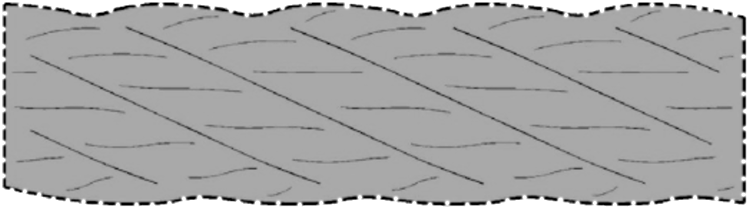
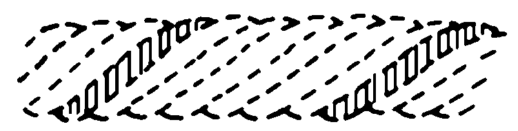
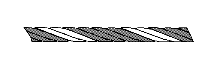
A hybrid rope constructed of a plurality of strands, wherein each strand is constructed of a fiber center, a jacket surrounding the fiber center, and a plurality of wires surrounding the jacket. The fiber center can be constructed of one or more high-strength synthetic fibers or yarns. The jacket can be constructed of polypropylene, thermoplastic polyurethane, high- density polyethylene, linear low-density polyethylene, nylon or other similar materials. The jacket can have a braided or woven design and adds a protective layer between the fiber center and the wires. The wires can be constructed of high-strength steel wires, galvanized steel or stainless steel. The fibers or yarns that make of the fiber center are twisted to lay right and then covered with the jacket. The wires then surround the jacket and are twisted to lay to the left. This creates a torque-balanced condition of the hybrid rope.
A hybrid rope constructed of a plurality of strands, wherein each strand is constructed of a fiber center, a jacket surrounding the fiber center, and a plurality of wires surrounding the jacket. The fiber center can be constructed of one or more high-strength synthetic fibers or yarns. The jacket can be constructed of polypropylene, thermoplastic polyurethane, high-density polyethylene, linear low-density polyethylene, nylon or other similar materials. The jacket can have a braided or woven design and adds a protective layer between the fiber center and the wires. The wires can be constructed of high-strength steel wires, galvanized steel or stainless steel. The fibers or yarns that make of the fiber center are twisted to lay right and then covered with the jacket. The wires then surround the jacket and are twisted to lay to the left. This creates a torque-balanced condition of the hybrid rope.
D07B 1/06 - Ropes or cables built-up from metal wires, e.g. of section wires around a hemp core
D07B 1/00 - Constructional features of ropes or cables
D07B 5/00 - Making ropes or cables from special materials or of particular form
D07B 1/14 - Ropes or cables with incorporated auxiliary elements, e.g. for making, extending throughout the length of the rope or cable
D07B 1/08 - Ropes or cables built-up from metal wires, e.g. of section wires around a hemp core the layers of which are formed of profiled interlocking wires, i.e. the strands forming concentric layers
The invention relates to a wire rope assembly unit, comprising a wire rope (4) and a device (1) for assembling the wire rope (4), which device is fastened at one end of the wire rope (4) and has a connecting element (2) that is arranged at the front on the end of the wire rope (4). The assembly unit (1) has a sleeve (3), which engages around an outer surface of an end section of the wire rope (4), the sleeve (3) preferably also engaging around the connecting element (2) in at least some regions. The sleeve (3) is made of a material, which is of lesser rigidity than strands (5, 6) of the wire rope (4) and, optionally, than the connecting element (2), and the sleeve (3) is pressed, hammered and/or rolled onto the wire rope (4) and, optionally, onto the connecting element (2) so as to produce a form-locked connection. In one embodiment of the invention, outer strands (6) of the wire rope (4) are separated from the wire rope (4) in a rope section, in which the wire rope (4) is arranged inside the sleeve (1), and the sleeve is connected, preferably welded, to ends of the outer strands (6) at its one edge.
F16G 11/02 - Means for fastening cables or ropes to one another or to other objectsCaps or sleeves for fixing on cables or ropes with parts deformable to grip the cable or cablesFastening means which engage a sleeve or the like fixed on the cable
38.
WIRE CABLE AND METHOD AND DEVICE FOR PRODUCTION OF SAID WIRE CABLE
The invention relates to a method for producing a wire cable (1), wherein a core strand (3) is compacted and then braid strands (2) are stranded on the core strand (3), characterized in that the core strand (3) is hammered before stranding of the braid strands (2) in order to smooth the surface (10) thereof. A plastic layer is advantageously applied to the core strand (3) before stranding of the braid strands (2), wherein the braid strands (2) are pressed into the plastic layer (7), preferably while the plastic layer (7) is heated. In the preferred embodiment of the invention, the core strand is a core cable (3) and the braid strands are strands (2) of the wire cable (1) or the core strand is a heart strand (3) and the braid strands are outer core strands of a core cable of the wire cable. A greater breaking strength of the wire cable (1) is obtained by hammering the core strand (3) in order to smooth it than by compacting a core strand (1) with a roller compressor. The invention further relates to the wire cable (1) and to a device for producing the wire cable (1).
06 - Common metals and ores; objects made of metal
Goods & Services
(1) Wire rope excluding any pool cover ropes, any ropes designed specifically for use with any swimming pool components and ropes designed specifically for use with swimming pool accessories.
41.
DEVICE AND METHOD FOR PRODUCING A STRAND OR A CABLE
The invention relates to a device for producing a strand or a cable (30), in particular a wire strand or wire cable, which device comprises a rotatable arrangement (2) for feeding cords (3, 4) to a twisting point (5) at which at which the cords (3, 4) are to be twisted with one another, and an installation (1) for heating at least one of the cords (3, 4). According to the invention the heating installation (1) is rotatable jointly with the feed arrangement (2). The heating installation (1) is advantageously designed to heat a cord (3) provided for forming a centre strand or a cable core and/or cords (4) for forming outer strands, and preferably comprises a burner (6) for fuel and/or an electrically operated heater (7).
The invention relates to a method for producing a rope (10), in particular a wire rope, a fibre rope or a rope having wire and fibres, wherein the rope (10) is provided with a marking during the braiding thereof. According to the invention, the marking is changed during the braiding operation. Expediently, during braiding, the marking is provided successively with details characterizing the braiding progress, said details comprising production parameters, for example information relating to the length of the rope (10) already formed, about raw materials used, the braiding speed and/or the current braiding time. The details are provided on a wire, a wire strand (6) and/or a marking strand (1), wherein the details are printed on the wire, the wire strand (6) or the marking strand (1) or are embossed in the wire, the wire strand (6) or the marking strand (15), and/or chips, preferably radio chips (15a), are arranged in the rope. The invention also relates to a device for carrying out the method and to the rope provided with the marking.
The invention relates to a force transmission unit (10) that has a rope (3), particularly a wire rope, and a device for introducing a force into the rope (3), comprising a sleeve (1) enclosing the rope (3) and connected to the rope (3) under deformation. The force transmission unit (10) according to the invention is characterised by a connecting member (2) which is arranged between the sleeve (1) and the rope (3) and formed from a material that has a lower strength than the materials from which the sleeve (1) and the outer strands of the rope (3) are formed and which preferably has a hollow cylindrical shape.
F16G 11/02 - Means for fastening cables or ropes to one another or to other objectsCaps or sleeves for fixing on cables or ropes with parts deformable to grip the cable or cablesFastening means which engage a sleeve or the like fixed on the cable
A rope having a cut-resistant jacket which includes a core comprised of a plurality of sub-ropes. The sub-ropes may be in a parallel strand configuration. The sub-ropes and the strands thereof may be made of fibers of a synthetic material, such as polyester, nylon, polypropylene, polyethylene, aramids, or acrylics. A cut-resistant jacket surrounds the core and is made from a material that has increased strength and/or abrasion resistance over the material of the core. The cut-resistant jacket may comprise steel wires and may further comprise braided steel wires or rope. The braided steel wires or rope may be covered with a plastic material for increased corrosion resistance. A filter layer may be disposed between the core and the cut-resistant jacket and may be wrapped around an outer surface of the core prior to the cut-resistant jacket being formed.
A rope having a cut-resistant jacket which includes a core comprised of a plurality of sub-ropes. The sub-ropes may be in a parallel strand configuration. The sub-ropes and the strands thereof may be made of fibers of a synthetic material, such as polyester, nylon, polypropylene, polyethylene, aramids, or acrylics. A cut-resistant jacket surrounds the core and is made from a material that has increased strength and/or abrasion resistance over the material of the core. The cut-resistant jacket may comprise steel wires and may further comprise braided steel wires or rope. The braided steel wires or rope may be covered with a plastic material for increased corrosion resistance. A filter layer may be disposed between the core and the cut-resistant jacket and may be wrapped around an outer surface of the core prior to the cut-resistant jacket being formed.
The invention relates to a device for producing a wire cable with two strand layers, comprising units (8-12) for preforming strands (1, 2) during the stranding of the cable, which units are adjustable in order to change the type and/or the size of the preforming. At least two (9; 11) of the units (8-12) are adjustable independently of one another. The device comprises a preforming head (3) that has for each strand (1, 2) a group (4, 5) of successive forming rollers (6) in the feed direction (z) of the strands (1, 2), the strands (1, 2) being movable along said groups in order to be shaped and the position of said groups relative to one another being adjustable, and wherein the position of the forming rollers (6) relative to one another can be set within at least one of the groups (4, 5) independently of the position of the forming rollers (6) of at least one of the other groups (4, 5) relative to one another. A corresponding method for preforming the strands of a two-layered wire cable is also disclosed.
06 - Common metals and ores; objects made of metal
22 - Rope, netting, tents, awnings, sails and sacks; padding and stuffing materials
Goods & Services
Wire rope, specialty wire, wire rope assemblies, high carbon wire Wire and synthetic fiber hybrid rope, high tenacity fiber rope, netting for use in the fishing industry, and synthetic rope
54.
METHOD FOR PRODUCING A STRAND OR CABLE WITH A THERMOPLASTIC COATING, STRAND OR CABLE PRODUCED BY THIS METHOD, AND TWISTING DEVICE WITH MEANS FOR COATING WITH THERMOPLASTICS
The invention relates to a method for producing a strand or cable (20), in which fibres (2) and/or wires are twisted at a twisting point (3) to form the strand or cable (20). The fibres (2) and/or wires are coated with a liquefied matrix material (4) before and/or at the twisting point (3) and are embedded in the matrix material (4) during twisting. The fibres (2) and/or wires are immersed in the matrix material before and/or at the twisting point (3) and the formed strand or the formed cable (20) is cooled after the twisting in order for the matrix material (4) to solidify, preferably by air or in a cooling liquid, for example water. The invention further relates to a device for carrying out the method and to a cable produced by the method.
D07B 7/14 - Machine detailsAuxiliary devices for coating or wrapping ropes, cables, or component strands thereof
D07B 1/16 - Ropes or cables with an enveloping sheathing or inlays of rubber or plastics
D07B 5/12 - Making ropes or cables from special materials or of particular form of low twist or low tension by processes comprising setting or straightening treatments
The present invention is directed to a wire rope having a blackened finish designed for theatrical productions. The wire rope includes a plurality of strands that have a closed spiral arrangement with each other and are compacted. Each strand includes a center wire spirally surrounded by a plurality of inner wires that are spirally surrounded by a plurality of outer wires so that the outer wires completely encompass the inner wires. The center wire and the inner wires are made from a galvanized material and coated with a lubricant. The outer wires are made from a non-coated steel material. Each strand is compacted so the outer wires create a tight mechanical seal to protect the inner wires. The blackened finish on the wire rope is due to a black oxide coating treatment and provides for low visibility of the wire rope during theatrical performances.
A socketing material (16), or mortar, for speltering wire rope, strand, and other tension members (14), comprising 35%-55% AL2O3; 32%-52% SiO2; 0%-20% CaO; and 0%-2% Fe2O3. The material (16) may have a continuous-use temperature of at least 1000 degrees, at least 2000 degrees, or at least 2500 degrees Fahrenheit. A speltered assembly (10) is produced by introducing the material (16) into and allowing it to cure within a cavity (24) of a terminal fitting (12) around the ends of a plurality of wires (31) of a tension member (16) which are arranged within the cavity (24) in a spaced-apart relationship.
The invention relates to a combined cable having a core cable made of high-strength plastic fibers present as a twisted monofilament bundle (1) or a plurality of twisted monofilament bundles (6), and having an external layer (2, 7) of steel wire strands (4, 5), characterized in that the monofilament bundle or bundles (1, 6) is or are stretched to reduce the diameter and held in a cladding (2, 7), particularly braided cladding, in this state. The strain of the core cable under load is thus reduced, so that the load distribution between the steel cross-section and the plastic cross-section of the cable is improved. In the same sense, in reverse, in order to have the strain behavior of the strand layer approach that of the core cable, the cable has an intermediate layer (3) made of an elastic plastic, in which the steel wire strands are pressed at a distance from each other, such that the external layer stretches under load and contracts radially.
3. The material (16) may have a continuous-use temperature of at least 1000 degrees, at least 2000 degrees, or at least 2500 degrees Fahrenheit. A speltered assembly (10) is produced by introducing the material (16) into and allowing it to cure within a cavity (24) of a terminal fitting (12) around the ends of a plurality of wires (31) of a tension member (16) which are arranged within the cavity (24) in a spaced-apart relationship.
In a first embodiment, a picture is taken of the traveling wire cable in a stationary position at intervals that are equal to the ratio produced from the lay length or a multiple of the lay length and the travel speed of the wire cable, at least on one lay length or the above-mentioned multiple of the lay length, and the successive images are compared on at least one lay length or the above-mentioned multiple of the lay length and are monitored for changes in the image which are indicative of damages. In a second embodiment, the wire cable is instead of taking pictures exposed to flashes and the exposed image is detected on at least one lay length or the above-mentioned multiple of the lay length and monitored for changes in the image. Preferably, the respective repetition of the same outer stranded wire of the traveling wire cable is detected in the same location and every repetition or every other repetition or every third repetition is used for triggering the taking of a picture or for triggering the flash. In a third embodiment, a picture is taken of a large portion of the wire cable using a specialized camera and the image is split up into recurring units of length that correspond to the size of a lay length or a multiple of the lay length and the successive units of length are compared and inspected for changes in the image.