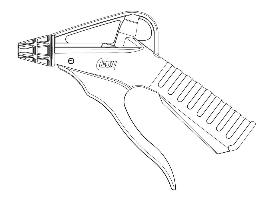
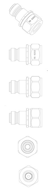
A blow gun comprising at least the following components is disclosed: a body; a handle; a nozzle; and a valve. Each component is detectable by an x-ray detector and a metal detector, and the handle acts directly on the valve. Any part of each component may be detectable by the x-ray detector and the metal detector. An assembly of the blow gun, a quick connect coupling, a hose, and a hose reel is disclosed. Each component of the coupling, the hose, and the hose reel may be detectable by an x-ray detector and a metal detector. By making each and every component and part of each component detectable by both an x-ray detector and a metal detector, the blow gun and any part thereof can be detected and therefore used in the food and beverage and medical industries.
B05B 1/00 - Nozzles, spray heads or other outlets, with or without auxiliary devices such as valves, heating means
B05B 1/30 - Nozzles, spray heads or other outlets, with or without auxiliary devices such as valves, heating means designed to control volume of flow, e.g. with adjustable passages
B05B 12/00 - Arrangements for controlling deliveryArrangements for controlling the spray area
A coupling configured to receive a nipple is disclosed. The coupling comprises a housing (100), the housing (100) comprising a circumferential set of balls (110), a spacer (120), and a spring (130); and a coupling body (200) at least partly within the housing (100), the coupling body (200) comprising a flange (210) with an inclined surface (212) and a surface (214). The coupling body (200) is arranged to be able to tilt with respect to the housing (100) and to receive the nipple. The inclined surface (212) engages one or more of the balls of the circumferential set of balls (110), the surface (214) engages the spacer (120), and the spring (130) provides a spring force forcing the spacer (120) against the flange (210). A corresponding nipple to receive a coupling is also disclosed.
A rotary viscous brake for a hose reel (10), and a hose reel (10) with the same, is disclosed. The rotary viscous brake (50) comprises a first part (100) attachable to a housing (20) of the hose reel (10), a second part (200) attachable to a rotatable drum (30) for a hose on the hose reel (10), and a third part (300) for enclosing the second part (200) within the first part (100) and third part (300) together with a liquid (400). The first part (100) comprises a plurality of first fins (110) being circumferential and extending in an axial direction of the rotary viscous brake (50). The second part (200) comprises a plurality of second fins (210) being at least partly circumferential and extending in an opposite axial direction of the rotary viscous brake (50). The plurality of first fins (110) and second fins (210) are arranged such that they are interleaved with each other and immersed by the liquid (400) for providing a damping torque when the first part (100) and the second part (200) rotate relatively to each other. There are at least two second fins (210) next to each circumferential first fin (110); and a thickness (220) of each of the second fins (210) is gradually increased from a thinner end (212) to a thicker end (214).
Coupling for connecting to a nipple (10), the coupling (20) comprising a body (100), a locking sleeve (200), and a plurality of locking elements (300). The body (100) being cylindrical about a central axis (110) and comprising a central passage (120) for the nipple and for the fluid. The locking sleeve (200) being cylindrical and slidably arranged on the outside of the body (100), the locking sleeve (200) comprising a plurality of release openings (210), or one circumferential release opening (210), for the plurality of locking elements (300). The plurality of locking elements (300) being arranged circumferentially in a plurality of openings (130) in the body (100), respectively. The shape of each of the plurality of locking elements (300) comprises a first segment (310) of a first right circular cylinder and a second segment (320) of a second right circular cylinder, the second segment (320) being larger than the first segment (310), and the first segment (310) being positioned on an apex of the second segment (320).
F16L 37/22 - Couplings of the quick-acting type in which the connection is maintained by means of balls, rollers, or helical springs under radial pressure between the parts
A system delivering hydraulic liquid for a hydraulic tool or machine at different controllable pressures and flows is disclosed. The system comprises an electric motor (100) comprising a rotor (110) and a stator (120); a pump (200), the pump being a plunger-type pump and comprising a cam (210), a cam shaft (220), a plunger (230), a plunger chamber (240), and a valve (250), the valve (250) opening or closing an inlet (260) for the hydraulic liquid to the plunger chamber (240), the plunger chamber (240) comprising an outlet (270), the plunger (230) engaging the cam (210), and the cam shaft (220) being connected to the rotor (110); a controller (300) configured to control the opening or closing of the valve (250) in relation to rotational position of the rotor (110) or cam (210) thereby controlling the volume and pressure of the hydraulic liquid to the outlet (270); and a pressure sensor (290) sensing pressure of the hydraulic liquid exiting the outlet (270). The controller (300) is further configured to open the valve (250) in relation to the rotational position of the cam (210) when the pressure sensor (290) senses a predetermined pressure of the hydraulic liquid thereby limiting the flow and pressure to the outlet (270).
F04B 1/053 - Multi-cylinder machines or pumps characterised by number or arrangement of cylinders having cylinders in star- or fan-arrangement with actuating or actuated elements at the inner ends of the cylinders
F04B 7/00 - Piston machines or pumps characterised by having positively-driven valving
F04B 9/04 - Piston machines or pumps characterised by the driving or driven means to or from their working members the means being mechanical the means being cams, eccentrics or pin-and-slot mechanisms
F04B 17/00 - Pumps characterised by combination with, or adaptation to, specific driving engines or motors
A system and method delivering hydraulic liquid at different predetermined and controllable pressures for a hydraulic tool or machine is disclosed. The system comprises an electric motor (100) comprising a rotor (110) and a stator (120); a pump (200), the pump being a plunger-type pump and comprising a cam (210), a cam shaft (220), a plunger (230), a plunger chamber (240), and a valve (250), the valve (250) opening or closing an inlet (260) for the hydraulic liquid to the plunger chamber (240), the plunger chamber (240) comprising an outlet (270) for the hydraulic liquid, the plunger (230) engaging the cam (210), and the cam shaft (220) being connected to the rotor (110); a pressure sensor (290) sensing pressure of the hydraulic liquid to be delivered; and a controller (300) configured to control the opening and closing of the valve (250) in relation to pressure sensed by the pressure sensor (300) and rotational position of the rotor (110) or cam (210), the controller (300) thereby controlling the volume and pressure of the hydraulic liquid to the outlet (270) and the load on the electric motor (100).
F04B 1/053 - Multi-cylinder machines or pumps characterised by number or arrangement of cylinders having cylinders in star- or fan-arrangement with actuating or actuated elements at the inner ends of the cylinders
F04B 7/00 - Piston machines or pumps characterised by having positively-driven valving
F04B 9/04 - Piston machines or pumps characterised by the driving or driven means to or from their working members the means being mechanical the means being cams, eccentrics or pin-and-slot mechanisms
F04B 17/03 - Pumps characterised by combination with, or adaptation to, specific driving engines or motors driven by electric motors
A system and a method for controlling a pump to deliver hydraulic liquid for a hydraulic tool or machine at different controllable pressures and flows are disclosed. The system comprises an electric motor (100) comprising a rotor (110) and a stator (120); a pump (200), the pump being a plunger-type pump and comprising a cam (210), a cam shaft (220), a plunger (230), a plunger chamber (240), and a valve (250), the valve (250) opening or closing an inlet (260) for the hydraulic liquid to the plunger chamber (240), the plunger chamber comprising an outlet (270) for the hydraulic liquid, the plunger (230) engaging the cam (210), and the cam shaft (220) being connected to the rotor (110); a pressure sensor (290) sensing pressure of the hydraulic liquid to be delivered; and a controller (300) comprising a processor (310), the processor (310) being configured to control the opening and closing of the valve (250) in relation to pressure sensed by the pressure sensor (290) and rotational position of the rotor (110) or cam (210), and the processor (310) being configured to control the rotational speed, rpm, of the motor (100), wherein the processor (310) is further configured to be programmable to set a delivery profile setting the duration of the valve (250) being closed and opened and the timing when to open or close of the valve (250) in relation to the rotation position of the rotor (110) or cam (210), the delivery profile comprising at least a predetermined pressure and flow relationship, over time, of the hydraulic liquid to be deliver.
F04B 1/053 - Multi-cylinder machines or pumps characterised by number or arrangement of cylinders having cylinders in star- or fan-arrangement with actuating or actuated elements at the inner ends of the cylinders
F04B 7/00 - Piston machines or pumps characterised by having positively-driven valving
F04B 9/04 - Piston machines or pumps characterised by the driving or driven means to or from their working members the means being mechanical the means being cams, eccentrics or pin-and-slot mechanisms
F04B 17/03 - Pumps characterised by combination with, or adaptation to, specific driving engines or motors driven by electric motors
F04B 49/20 - Control of, or safety measures for, machines, pumps, or pumping installations, not otherwise provided for in, or of interest apart from, groups by changing the driving speed
8.
System and method for centralizing a quick connect nipple
A system for centralizing a quick connect coupling is disclosed. The system comprises a housing; a quick connect coupling comprising a first circumferential part cone-shaped surface; and a hose connection, comprising a second circumferential part cone-shaped surface. The system comprises a first centralizing ring having a third circumferential part cone-shaped surface engaging the first circumferential part cone-shaped surface of the quick connect coupling; and a second centralizing ring having a surface engaging with the second circumferential part cone-shaped surface of the hose connection. The system comprises a spring forcing the third circumferential part cone-shaped surface of the first centralizing ring and the first circumferential part cone-shaped surface of the quick connect coupling, against each other, and forcing the surface of the second centralizing ring and the second circumferential part cone-shaped surface of the hose connection against each other.
F16L 37/52 - Universal joints, i.e. with a mechanical connection allowing angular movement or adjustment of the axes of the parts in any direction
F16L 29/04 - Joints with fluid cut-off means with a cut-off device in each of the two pipe ends, the cut-off devices being automatically opened when the coupling is applied
F16L 37/32 - Couplings of the quick-acting type with fluid cut-off means with fluid cut-off means in each of two pipe-end fittings at least one of two lift valves being opened automatically when the coupling is applied
F16L 37/38 - Couplings of the quick-acting type with fluid cut-off means with fluid cut-off means in only one of two pipe-end fittings
A blow gun comprising at least the following components is disclosed: a body (10); a handle (12); a nozzle (14); and a valve (16). Each component is detectable by an x- ray detector and a metal detector, and the handle (12) acts directly on the valve (16). Any part of each component may detectable by the x-ray detector and the metal detector. An assembly of the blow gun and a quick connect coupling (24) and a hose (36) and a hose reel (38) is disclosed. Each component of the coupling (24), the hose (36), and the hose reel (38) may be detectable by an x-ray detector and a metal detector. By making each and every component and part of each component detectable by both an x-ray detector and a metal detector, the blow gun and any part thereof can be detected and therefore used in the food and beverage and medical industries.
B05B 1/00 - Nozzles, spray heads or other outlets, with or without auxiliary devices such as valves, heating means
B08B 5/02 - Cleaning by the force of jets, e.g. blowing-out cavities
B05B 1/30 - Nozzles, spray heads or other outlets, with or without auxiliary devices such as valves, heating means designed to control volume of flow, e.g. with adjustable passages
A nipple that includes: a fluid passage; a housing; a valve for the fluid passage; and a relief valve for the valve. The relief valve may include: a first sleeve axially movable for sealing against a first seal of the housing; a second sleeve for sealing against a second seal of the housing; and a third seal for sealing between the first sleeve and the second sleeve. Relative axial movement between the first sleeve and the second sleeve opens or closes, respectively by the direction of the axial movement. The relief valve, the first seal, and the third seal are arranged at a set radial distance from a central axis of the fluid passage.
F16L 37/34 - Couplings of the quick-acting type with fluid cut-off means with fluid cut-off means in each of two pipe-end fittings at least one of two lift valves being opened automatically when the coupling is applied at least one of the lift valves being of the sleeve type, i.e. a sleeve being telescoped over an inner cylindrical wall
F16L 37/23 - Couplings of the quick-acting type in which the connection is maintained by means of balls, rollers, or helical springs under radial pressure between the parts by means of balls
F16L 37/56 - Couplings of the quick-acting type for double-walled or multi-channel pipes
Various embodiments include an adapter between two connectors and a coaxial coupling or a coaxial nipple. The two connectors are any combination of a separate coupling and a separate nipple. The adapter may include: a body with two cylindrical openings; a first element that fits in the first opening with connections for a first of the two connectors and the coaxial coupling or nipple; and a second element that fits in the second cylindrical opening, and a third connection for the other connector. The first element slides and rotates in the body and has a central axis eccentric to a central axis of the cylindrical first element part. The second element slides and rotates in the body. The central axis of the third connection is eccentric to a central axis of the cylindrical second element part.
F16L 21/02 - Joints with sleeve or socket with elastic sealing rings between pipe and sleeve or between pipe and socket, e.g. with rolling or other prefabricated profiled rings
F16L 39/04 - Joints or fittings for double-walled or multi-channel pipes or pipe assemblies allowing adjustment or movement
F16L 27/12 - Adjustable jointsJoints allowing movement allowing substantial longitudinal adjustment or movement
F16L 37/26 - Couplings of the quick-acting type in which the connection is made by transversely moving the parts together, with or without their subsequent rotation
F16L 37/413 - Couplings of the quick-acting type with fluid cut-off means with fluid cut-off means in only one of two pipe-end fittings with a lift valve being opened automatically when the coupling is applied the lift valve being of the sleeve type, i.e. a sleeve being telescoped over an inner cylindrical wall
F16L 37/42 - Couplings of the quick-acting type with fluid cut-off means with fluid cut-off means in only one of two pipe-end fittings with a lift valve being opened automatically when the coupling is applied the valve having an axial bore communicating with lateral apertures
F16L 37/50 - Couplings of the quick-acting type adjustableCouplings of the quick-acting type allowing movement of the parts joined
F16L 37/56 - Couplings of the quick-acting type for double-walled or multi-channel pipes
F16L 55/07 - Arrangement or mounting of devices, e.g. valves, for venting or aerating or draining
G02B 6/38 - Mechanical coupling means having fibre to fibre mating means
13.
SYSTEM AND METHOD FOR CENTRALIZING A QUICK CONNECT NIPPLE
A system for centralizing a quick connect nipple or a quick connect coupling is disclosed. The system comprises a housing (10); a quick connect nipple (20), or a quick connect coupling, each comprising a first circumferential part cone-shaped surface (22); and a hose connection (30), comprising a second circumferential part cone-shaped surface (32). The system comprises a first centralizing ring (110) having a third circumferential part cone-shaped surface (112) engaging the first circumferential part cone-shaped surface (22) of the quick connect nipple (20) or the quick connect coupling; and a second centralizing ring (120) having a surface (122) engaging with the second circumferential part cone-shaped surface (32) of the hose connection (30). The system comprises a spring (130) forcing the third circumferential part cone-shaped surface (112) of the first centralizing ring (110) and the first circumferential part cone-shaped surface (22) of the quick connect nipple (20), or the quick connect coupling, against each other, and forcing the surface (122) of the second centralizing ring (120) and the second circumferential part cone- shaped surface (32) of the hose connection (30) against each other. A method for centralizing the nipple or coupling is also disclosed, as well as a method of assembling the system.
F16L 29/04 - Joints with fluid cut-off means with a cut-off device in each of the two pipe ends, the cut-off devices being automatically opened when the coupling is applied
F16L 37/367 - Couplings of the quick-acting type with fluid cut-off means with fluid cut-off means in each of two pipe-end fittings with two gate valves or sliding valves
F16L 37/52 - Universal joints, i.e. with a mechanical connection allowing angular movement or adjustment of the axes of the parts in any direction
Disclosed is a floating coupling comprising a coupling (100), a housing (200), and a spring (250), the spring (250) being arranged between the coupling (100) and the housing (200). The coupling (100) comprises an outer circumferential surface (110) forming an angle (300) between 10 and 80 degrees with a central axis (310) of the coupling (100). The housing (200) comprises a cylindrical opening (220) for accommodating the coupling (100), the inside of the opening (220) comprising an inner circumferential surface (210), complementary to the outer circumferential surface (110), forming an corresponding angle (300) between 10 and 80 degrees with the central axis (310) of the coupling. The spring (250) forces the coupling (100) so that the outer circumferential surface (110) engages the inner circumferential surface (210) centralising the coupling (100) in the housing (200). A corresponding floating nipple is also disclosed.
F16L 29/02 - Joints with fluid cut-off means with a cut-off device in one of the two pipe ends, the cut-off device being automatically opened when the coupling is applied
F16L 37/50 - Couplings of the quick-acting type adjustableCouplings of the quick-acting type allowing movement of the parts joined
Various embodiments of the teachings herein include a pulse counter for fluid pressure changes. The pulse counter may include: a first and a second housing part with a fluid passage; a circuit board at least partially enclosed within the housing, the circuit board comprising a light pulse transmitter and a light pulse receiver; a battery at least partially within the housing, the battery supplying electric power to the light pulse transmitter and the light pulse receiver; a rod slidably arranged within the housing, with one end of the rod within the fluid passage, and a second end arranged at least partly breaking a light pulse between the light pulse transmitter and the light pulse receiver; and a spring forcing the rod away from the light pulse and towards the fluid passage.
G01L 23/06 - Indicating or recording by optical means
G01L 11/02 - Measuring steady or quasi-steady pressure of a fluid or a fluent solid material by means not provided for in group or by optical means
G01L 23/02 - Devices or apparatus for measuring or indicating or recording rapid changes, such as oscillations, in the pressure of steam, gas, or liquidIndicators for determining work or energy of steam, internal-combustion, or other fluid-pressure engines from the condition of the working fluid mechanically indicating or recording and involving loaded or return springs
A coupling for a nipple is disclosed. The coupling comprises a main body (100); and an opening (110), for a fluid, in the main body (100), the opening (110) being cylindrical. The coupling comprises further a holder (130) arranged in the opening (110) holding a plurality of locking elements (140) for locking the nipple to the coupling, the holder (130) and the plurality of locking elements (140) being separate; and a retaining element (150) retaining the holder (130) in the opening (110), the retaining element (150) engaging the plurality of locking elements (140). A method for assembling such a coupling is disclosed. The method comprises inserting the holder (130) with the locking means (140) into the main body (100); and retaining the holder (130) in the main body (100) with the retaining means (150).
F16L 37/098 - Couplings of the quick-acting type in which the connection between abutting or axially-overlapping ends is maintained by locking members combined with automatic locking by means of flexible hooks
A nipple comprising only one fluid passage, or more, such as an inner fluid passage (100) and an outer fluid passage (200), the inner and outer fluid passages being coaxial. The nipple comprises a housing (10); an inner valve (110) for the inner fluid passage (100); and an outer valve (210) for the outer fluid passage (200). The nipple also comprises an outer relief valve (220) for the outer valve (210), the outer relief valve (220) comprising a first sleeve (230) axially movable for sealing against a first seal (232) of the housing (10); a second sleeve (240) axially movable for sealing against a second seal (242) of the housing (10); and a third seal (222) for sealing between the first sleeve (230) and the second sleeve (240). Relative axial movement between the first sleeve (230) and the second sleeve (240) opens or closes, respectively by the direction of the axial movement, the outer relief valve (220), the first seal (232) and the third seal (222) being arranged substantially on the same radial distance from a common axis (20) of the inner fluid passage (100) and the outer fluid passage (200). The Nipple may comprise an inner relief valve (120) for the inner valve (110). The nipple may comprise a locking groove (300) on an outer side of the housing (10), the locking groove being circumferential around the housing (10) and having a shape substantially as a combination of two intersecting and stepped U shaped grooves.
F16L 37/34 - Couplings of the quick-acting type with fluid cut-off means with fluid cut-off means in each of two pipe-end fittings at least one of two lift valves being opened automatically when the coupling is applied at least one of the lift valves being of the sleeve type, i.e. a sleeve being telescoped over an inner cylindrical wall
F16L 37/56 - Couplings of the quick-acting type for double-walled or multi-channel pipes
F16L 37/23 - Couplings of the quick-acting type in which the connection is maintained by means of balls, rollers, or helical springs under radial pressure between the parts by means of balls
A pulse counter for counting fluid pressure changes is disclosed. The pulse counter comprises a first housing part (10); a second housing part (20) comprising a fluid passage (22), the first housing part (10) being separate from the second housing part (20); a circuit board (30) within the two housing parts (10, 20), the circuit board (30) comprising a light pulse transmitter (32) and a light pulse receiver (34); a battery (40) within the two housing parts (10, 20), the battery (40) supplying electric power to the light pulse transmitter (32) and the light pulse receiver (34); a rod (50) slidably arranged between the first housing part (10) and the second housing part (20), with one end (52) of the rod (50) within the fluid passage (22), and another end (54) of the rod (50) arranged for at least partly breaking a light pulse (33) between the light pulse transmitter (32) and the light pulse receiver (34); and a spring (60) forcing the rod (50) away from the light pulse (33) and towards the fluid passage (20). A method for counting fluid pulses using such a pulse counter is also disclosed. The method comprises setting (510) the pressure level that moves the rod (50) to at least partly break the light pulse (33) by setting the force of the spring (60) and by selecting a diameter (58) of the end (52) of the rod (50) within the fluid passage (20).
A locking mechanism for a quick connect coupling includes a locking sleeve that is axially displaceable for locking the quick connect coupling in a locked position and for unlocking the quick connect coupling in an unlocked position. The locking mechanism comprises a safety ring, the safety ring is axially displaceable for engaging the locking sleeve and the safety ring being partly inside or partly outside the locking sleeve. The safety ring being positionable in three different axial positions, a first axial position for allowing the locking sleeve to be in the unlocked position, a second axial position for allowing the safety ring to rotate, and a third axial position for allowing the locking sleeve to be in the locked position. The locking mechanism comprises a spring, the spring acting between the locking sleeve and the safety ring. The spring comprising a spring force forcing the locking sleeve and the safety ring away from each other. Methods using the locking mechanism are also provided.
F16L 37/23 - Couplings of the quick-acting type in which the connection is maintained by means of balls, rollers, or helical springs under radial pressure between the parts by means of balls
F16L 37/34 - Couplings of the quick-acting type with fluid cut-off means with fluid cut-off means in each of two pipe-end fittings at least one of two lift valves being opened automatically when the coupling is applied at least one of the lift valves being of the sleeve type, i.e. a sleeve being telescoped over an inner cylindrical wall
A coupling for a nipple is disclosed. The coupling comprises a main body (100); and an opening (110), for a fluid, in the main body (100), the opening (110) being cylindrical. The coupling comprises further a holder (130) arranged in the opening (110) holding a plurality of locking elements (140) for locking the nipple to the coupling, the holder (130) and the plurality of locking elements (140) being separate; and a retaining element (150) retaining the holder (130) in the opening (110), the retaining element (150) engaging the plurality of locking elements (140). A method for assembling such a coupling is disclosed. The method comprises inserting the holder (130) with the locking means (140) into the main body (100); and retaining the holder (130) in the main body (100) with the retaining means (150).
F16L 37/084 - Couplings of the quick-acting type in which the connection between abutting or axially-overlapping ends is maintained by locking members combined with automatic locking
F16L 37/096 - Couplings of the quick-acting type in which the connection between abutting or axially-overlapping ends is maintained by locking members combined with automatic locking by means of hooks hinged about an axis
F16L 37/091 - Couplings of the quick-acting type in which the connection between abutting or axially-overlapping ends is maintained by locking members combined with automatic locking by means of a ring provided with teeth or fingers
F16L 37/098 - Couplings of the quick-acting type in which the connection between abutting or axially-overlapping ends is maintained by locking members combined with automatic locking by means of flexible hooks
An LED (light-emitting diodes) light hose reel is disclosed, comprising a housing (10); a reel (12) inside the housing (10); a transparent hose (20), the hose (20) being retractably reeled on the reel (12) inside the housing (10); an LED light strip (22) arranged inside the hose (20); an electric power cable (34) for the LED light strip (22); and an electric connection (36) between the LED light strip (22) and the electric power cable (34). A method of storing an LED light strip is disclosed, comprising storing the LED light strip on a retractable reel. A method of using the LED light hose reel is disclosed. The method comprising the following steps in any order: withdrawing the hose (20) from the LED light hose reel; selecting light colour and selecting blinking or constant light by activating the control element (32); attaching the hose (20) to an object; and retracting the hose (20) into the LED light hose reel.
F21V 27/00 - Cable-stowing arrangements structurally associated with lighting devices, e.g. reels
F21S 4/26 - Lighting devices or systems using a string or strip of light sources with light sources held by or within elongate supports flexible or deformable, e.g. into a curved shape of rope form, e.g. LED lighting ropes, or of tubular form
F21V 33/00 - Structural combinations of lighting devices with other articles, not otherwise provided for
B65H 75/00 - Storing webs, tapes, or filamentary material, e.g. on reels
F21V 17/00 - Fastening of component parts of lighting devices, e.g. shades, globes, refractors, reflectors, filters, screens, grids or protective cages
F21V 23/06 - Arrangement of electric circuit elements in or on lighting devices the elements being coupling devices
F21W 111/00 - Use or application of lighting devices or systems for signalling, marking or indicating, not provided for in groups
F21Y 107/70 - Light sources with three-dimensionally disposed light-generating elements on flexible or deformable supports or substrates, e.g. for changing the light source into a desired form
F21Y 109/00 - Light sources with light-generating elements disposed on transparent or translucent supports or substrates
22.
NIPPLE FOR SCREW TO CONNECT COUPLING, COUPLING, AND METHOD FOR CONNECTING THE NIPPLE
A nipple for a screw to connect coupling is disclosed. The nipple being a hand held mobile nipple, comprises a locking sleeve (10) having one or more threads (12) for a screw connection of a coupling, and the locking sleeve (10) having a gear (20); a gear housing (30) having one or more pinions (22) meshing the gear (20), the one or more pinions having means (24) for connecting to an external rotational tool; a nipple body (40) rotationally supporting the locking sleeve (10), and the nipple body (40) supporting the gear housing (30); and a stop (50) preventing relative rotation between the nipple body (40) and the gear housing (30). A method for connecting such a nipple and a coupling of a screw to connect coupling is also disclosed. The method comprises aligning the nipple and the coupling to engage the screw connection; apply a hand held electric rotational power tool (80) to the means (24) for connecting to an external rotational tool; and operate the hand held electric rotational power tool (80) to rotate the locking sleeve (10) thereby connecting the nipple with the coupling of the screw to connect coupling.
F16L 29/04 - Joints with fluid cut-off means with a cut-off device in each of the two pipe ends, the cut-off devices being automatically opened when the coupling is applied
23.
Assembly of a coupling and a stiff tube and method therefore
An assembly of a male coupling part 200 and a stiff tube 100 is disclosed, the stiff tube 100 having an attachment means 110; and the male coupling part 200 requiring a relative axial displacement between the male coupling part 200 and the stiff tube 100 for connecting to a female coupling part 500, the male coupling part 200 comprising an axial through opening 210. The Assembly further comprises an element 300 detachably connected to the male coupling part 200 and slidably attached to the stiff tube 100, the element 300 having an opening 310 allowing relative axial displacement 340 between the male coupling part 200 and the stiff tube 100, and the attachment means 110 being movable within the opening 310. A method for coupling and un-coupling the assembly to a female coupling part is also disclosed.
F16L 37/50 - Couplings of the quick-acting type adjustableCouplings of the quick-acting type allowing movement of the parts joined
F16L 27/12 - Adjustable jointsJoints allowing movement allowing substantial longitudinal adjustment or movement
F16L 37/096 - Couplings of the quick-acting type in which the connection between abutting or axially-overlapping ends is maintained by locking members combined with automatic locking by means of hooks hinged about an axis
06 - Common metals and ores; objects made of metal
07 - Machines and machine tools
08 - Hand tools and implements
09 - Scientific and electric apparatus and instruments
17 - Rubber and plastic; packing and insulating materials
37 - Construction and mining; installation and repair services
Goods & Services
Couplings and connectors of metal for pipes, tubes and hoses; valves of metal, other than parts of machines; non-mechanical reels of metal for storing cables or hoses; fittings of metal for compressed air lines; nozzles of metal; seals of metal for preventing leakage of gases; sealing caps of metal; metal nipples; hose reels of metal (non mechanical); metal collars, nuts, adapters, plugs, caps and tubing; metal hose restraint. Couplings and connectors, other than for land vehicles; machine coupling and transmission components, other than for land vehicles; hydraulic couplings, other than for land vehicles; safety couplings, other than for land vehicles; couplings for machines and machine tools; couplings of metal for agricultural implements; couplings for pneumatic and hydraulic apparatus; fluid couplings being parts of machines; adaptors for pipes, being parts of machines; pneumatic tools; hydraulic tools; mechanical tools; powered tools; air driven hand tools; compressed air machines; power-operated sprayers; air and fluid guns; power-operated blow guns; nozzles for blow guns; fluid pumps; high pressure pumps; machine pumps; guns for compressed liquid spraying machines; spray nozzles being parts of machines; valves; valves for machines; hydraulic valves; regulators being parts of machines; pressure regulators and controllers, being parts of machines; mechanical hose reels; mechanical seals being parts of machines. Hand-operated hand tools; guns [hand tools]; hand-operated spray guns; hand operated blow guns; hand pumps. Pressure gauges; pressure regulators; pressure sensors; pressure controls; sensors and detectors; electronic sensors; sensors for use with machines and machine tools; electronic chips for the provision of technical data via connection to a computer software application; computer software for the provision of technical data relating to machines and machine tools; databases. Flexible pipes, tubes, hoses, valves and fittings, all non- metallic; hoses, air hoses, rubber hoses; non-metallic pressure hoses; couplings; non-metallic pipe and hose couplings; non-metallic couplings for use with high pressure hoses; compressed air pipe fittings [not of metal]; fluid seals. Maintenance, servicing and repair of machines and machine tools; maintenance, servicing and repair of high-pressure equipment; maintenance, servicing and repair of couplings and connectors for machines and hoses; rental of equipment, machines and machine tools; rental of couplings, valves, tubes, hoses, and pipes.
A locking mechanism for a quick connect coupling having a locking sleeve (100) is disclosed. The locking sleeve is axially displaceable for locking the quick connect coupling in a locked position (110) and for unlocking the quick connect coupling in an unlocked position (120). The locking mechanism comprises a safety ring (200), the safety ring (200) is axially displaceable for engaging the locking sleeve (100) and the safety ring (200) being partly inside or partly outside the locking sleeve (100). The safety ring being positionable in three different axial positions, a first axial position (210) for allowing the locking sleeve (100) to be in the unlocked position (120), a second axial position (220) for allowing the safety ring (200) to rotate, and a third axial position (230) for allowing the locking sleeve(100) to be in the locked position (110). The locking mechanism comprises a spring (300), the spring acting between the locking sleeve (100) and the safety ring (200). The spring (300) comprising a spring force forcing the locking sleeve (100) and the safety ring (200) away from each other. Methods using the locking mechanism are also disclosed.
F16L 37/10 - Couplings of the quick-acting type in which the connection between abutting or axially-overlapping ends is maintained by locking members using a rotary external sleeve or ring on one part
F16L 37/23 - Couplings of the quick-acting type in which the connection is maintained by means of balls, rollers, or helical springs under radial pressure between the parts by means of balls
A multicoupling comprising a first and second part comprising a first and second set of connectors; and rotational means for connecting the first part and second part. The first set of connectors comprise a plurality of couplings, or a plurality of nipples, or at least one coupling and at least one nipple, or at least one electric contact and at least one of a coupling or a nipple. The second set of connectors comprise, correspondingly, a plurality of couplings, or a plurality of nipples, or at least one coupling and at least one nipple, or at least one electric contact and at least one of a coupling or a nipple. The rotational means actuates, by rotation, control means for at least one connector of the first and/or second set of connectors, and the rotational means and the control means are in one and the same first part or second part.
F16L 37/23 - Couplings of the quick-acting type in which the connection is maintained by means of balls, rollers, or helical springs under radial pressure between the parts by means of balls
H01R 13/00 - Details of coupling devices of the kinds covered by groups or
F16L 37/56 - Couplings of the quick-acting type for double-walled or multi-channel pipes
A stop ball for a tube for fluid or energy is provided. The stop ball comprises a singular hollow body. The hollow body comprises and is integral with a first opening for the tube and an attachment means for attaching the stop ball to the tube, the attachment means comprising a second opening for the tube. A method for attaching a stop ball according to any one of the preceding embodiments to a tube for fluid or energy is provided. The method comprising inserting the tube through all three openings; pulling the attachment means at least partly out of the hollow body; and clamping the attachment means onto the tube.
A hose reel, for reeling up a hose for a fluid, is disclosed. The hose reel comprises a drum (100) for the hose to be reeled up on, the drum being moulded, the drum comprising, as integral moulded parts, a swivel connector (120) arranged at a central axis (110), the drum being rotatable about the central axis, a central flow path (130) coaxial with the central axis (110), and a radial flow path (140) extending radially from the central flow path; and a swivel (200) for a supply of the fluid, the swivel being connected to the swivel connector. A method for connecting a hose to the hose reel is disclosed. The method comprises the steps of: rotating the drum to align the connector (300) with the opening (410) of the housing (400); and connecting a hose to the connector, alternatively, before connecting the hose, releasing an already present hose.
A junction box, for electricity and fluid, mountable on a vehicle is disclosed. The junction box (100) comprises a housing (110), the housing having a disk shaped front face (112); one or more fluid ejectors (120), the one or more fluid ejectors being able to be activated by an electric circuit of the vehicle; one electric coupling (130); one fluid coupling (140); one indicator for indicating electric power supply (150); and one indicator for indicating fluid pressure (160). The one or more fluid ejectors, the electric coupling, the fluid coupling, and the two indicators are all arranged within the disk shaped front face of the housing. Further, a connector, for electricity and fluid, connectable to the junction box is disclosed. The connector comprises a body (210), the body having a disk shaped front face (212); a handle (220) attached to the body; a first opening for one electric coupling (230); a second opening for one fluid coupling (240); one indicator for indicating electric power supply (250); and one indicator for indicating fluid pressure (260). The first and second openings, and the two indicators are all arranged within the disk shaped front face of the body. Furthermore, a method for ejecting the connector from the junction box is disclosed.
H01R 13/00 - Details of coupling devices of the kinds covered by groups or
H01R 13/637 - Additional means for facilitating engagement or disengagement of coupling parts, e.g. aligning or guiding means, levers, gas pressure for disengagement only by fluid pressure, e.g. explosion
B60L 11/18 - using power supplied from primary cells, secondary cells, or fuel cells
06 - Common metals and ores; objects made of metal
07 - Machines and machine tools
08 - Hand tools and implements
09 - Scientific and electric apparatus and instruments
17 - Rubber and plastic; packing and insulating materials
Goods & Services
Hand-operated reels of metal for flexible hoses; metal couplings for use with hydraulic and pneumatic systems; couplings of metal for pipes and tubes; connectors of metal for pipes and tubes; metal pipe couplings and joints; non-electronic metal adapters for pipes; metal adapters for use with hydraulic and pneumatic systems; nozzles of metal, namely, non-automatic fueling nozzles; metal, wash down spray nozzles for commercial and industrial use; seals of metal for preventing leakage of gases; sealing caps of metal; valves of metal, other than parts of machines; manually operated metal valves Couplings for machines; machine tool couplings; couplings for pneumatic machines; couplings for hydraulic machines; safety couplings for machines; fluid couplings being parts of machines; couplings of metal for agricultural machines; machine coupling and transmission components except for land vehicles; spraying machines; power operated sprayers; hand held power operated spraying machines; compressed air spraying machines; compressed air machines; power-operated spray guns; power-operated spray guns for compressed air spraying machines; compressed liquid spraying machines; power-operated spray guns for compressed liquid spraying machines; spray nozzles being parts of machines; machine parts, namely, nozzles which are parts of power-operated sprayers; parts for compressed air tools, namely, brakes, filters, hoses, pipes, couplings valves, switches, compressors, clamping tools and injectors; mechanical, power-operated hose reels; machine parts, namely, mechanical seals; valves being parts of machines; hydraulic valve actuators; pneumatic valve actuators; compressed air pumps; high-pressure pumps for use in oil or gas well hydraulic fracturing operations; high-pressure pumps for washing appliances and installations; hydraulic pumps; pneumatic pumps; pumps as parts of machines, motors and engines; air filters for mechanical purposes; air filters for pneumatic machines; pressure regulators being parts of machines; pressure controllers being parts of machines; pressure transducers as parts of machines; pressure switches as parts of machines; adaptors for tool bits being parts of machines; adaptors for pipes being parts of machines Hand-operated spray guns; hand-operated pumps; hand tools, namely, hand-operated air pumps Electric couplings; nozzles of metal, namely, automatic nozzles; Measuring couplings for measuring temperature, pressure, quantity and concentration of fluids in hydraulic or pneumatic systems; High-pressure pumps for proportioning and testing purposes Air Hoses; rubber hoses for industrial applications; hoses for pneumatic tools; hydraulic hoses made of rubber; flexible hoses composed of plastics; non-metallic pressure air hoses; non-metal, non-electric couplings for hoses; non-metal pipe couplings and joints; non-metallic connectors for hoses being non-metal hose fittings; non-metallic flexible pipes, tubes and watering hoses; fittings, not of metal, for flexible pipes and hoses; non-metal hose fittings; fittings, not of metal, for compressed air hoses
06 - Common metals and ores; objects made of metal
07 - Machines and machine tools
12 - Land, air and water vehicles; parts of land vehicles
Goods & Services
Quick-connect couplings of metal for pipes, tubes and hoses. Quick-connect couplings, other than for land vehicles; quick-connect hydraulic couplings, other than for land vehicles; quick-connect safety couplings, other than for land vehicles; quick-connect couplings of metal for machines and machine tools; quick-connect couplings of metal for agricultural implements; quick-connect couplings for pneumatic and hydraulic apparatus. Quick-connect couplings for land vehicles.
Connector for fluid, connectable by a remotely operated vehicle, ROV, includes a first part including a first cam element including an opening and a cam for engagement of a protrusion, the first cam element and the cam being rotably arranged relative to the first part; a second part includes a second cam element for insertion into the opening, the second cam element including the protrusion for the cam; a clutch between the first cam element and a handle to be held by the ROV; an indicator on the first part to indicate correct position for connecting, and disconnecting, the first part with, or from, the second part with the first and second cam elements; and an emergency release mechanism to disconnect the first part from the second part.
A nipple for a coaxial coupling is disclosed. The nipple comprises a housing (40), and a nipple tube (30) arranged in the housing (40). The nipple comprises a first passage (42) between the housing (40) and the nipple tube (30), and the nipple tube (30) comprising a second passage (32) within the nipple tube (30). A relief valve (20) is slideably arranged in the nipple tube (30). The nipple comprises sealing means (24, 26) for sealing between the nipple tube (30) and the relief valve (20). The nipple tube (30) further comprises a relief passage (34), the relief passage (34) forming a fluid passage between the first passage (42) and the second passage (32). The relief passage (34) being arranged so that the sealing means (24, 26) seals the relief passage (34) when the nipple is fully coupled.
B25B 21/00 - Portable power-driven screw or nut setting or loosening toolsAttachments for drilling apparatus serving the same purpose
F16L 37/42 - Couplings of the quick-acting type with fluid cut-off means with fluid cut-off means in only one of two pipe-end fittings with a lift valve being opened automatically when the coupling is applied the valve having an axial bore communicating with lateral apertures
F16L 37/56 - Couplings of the quick-acting type for double-walled or multi-channel pipes
F16L 39/04 - Joints or fittings for double-walled or multi-channel pipes or pipe assemblies allowing adjustment or movement
Coupling for a supply fluid and a return fluid comprising a swivel part (300), a first part (100), and a second part (200). The swivel part (300) comprises a rotational axis (350) and a swivel part first channel inside the swivel part (300) for the supply fluid. The first part (100) comprises a first opening for the swivel part (300), a first part first channel for the supply fluid, and a first part second channel for the return fluid. The first part (100) being configured to receive the supply fluid and to return the return fluid. The second part (200) comprises a second opening for the swivel part (300), a second part first channel for the supply fluid, and a second part second channel for the return fluid. The second part being configured to receive a rotatable coupling (400). The swivel part (300) arranging the first part (100) and the second part (200) rotatably relative to each other. The first opening holding substantially a continuous half the swivel part (300) and the second opening holding substantially the other continuous half of the swivel part (300).
A tube comprising a tag (30). The tag (30) comprising tube service data and at least one more data of the following group of data: tube identification data, tube manufacture data, and tube operation data. The tag (30) allows the data to be read, written, and updated electronically, and the tag (30) provides data for servicing the tube (10). A method for servicing such a tube, the method comprising: providing the tag (30) on the tube (10); reading electronically the data from the tag (30) for servicing the tube (10); servicing the tube (10) according to the data read; and writing electronically the data to the tag (30) to update at least the tube service data.
F16L 55/00 - Devices or appurtenances for use in, or in connection with, pipes or pipe systems
F16L 1/11 - Accessories therefor, e.g. anchors for the detection or protection of pipes in the ground
F16L 11/12 - Hoses, i.e. flexible pipes made of rubber or flexible plastics with arrangements for particular purposes, e.g. specially profiled, with protecting layer, heated, electrically conducting
G01V 15/00 - Tags attached to, or associated with, an object, in order to enable detection of the object
G06K 19/077 - Constructional details, e.g. mounting of circuits in the carrier
A tube comprising a tag (30). The tag (30) comprising tube service data and at least one more data of the following group of data: tube identification data, tube manufacture data, and tube operation data. The tag (30) allows the data to be read, written, and updated electronically, and the tag (30) provides data for servicing the tube (10). A method for servicing such a tube, the method comprising: providing the tag (30) on the tube (10); reading electronically the data from the tag (30) for servicing the tube (10); servicing the tube (10) according to the data read; and writing electronically the data to the tag (30) to update at least the tube service data.
This invention relates to a coupling comprising a male part and a female part (7, 9), each having a ducting system (39) for the transmission of fluid (F) during the use of the coupling (1, 1′, 2), at least a front portion (13) comprising a main valve member (19) designed to prevent the fluid (F) from leaving the ducting system (39) when the coupling (1, 1′, 2) is uncoupled. An operating member (5) is connected to a pilot valve member (41, 63, 63″, 64) for controlling the flow of fluid (F) to and for pressurizing a valve chamber (45, 45″) in which a pressure relief valve member (33, 33′, 35, 35″) is designed to move into a position in which the ducting system (39) is opened or throttled.
F16L 37/30 - Couplings of the quick-acting type with fluid cut-off means with fluid cut-off means in each of two pipe-end fittings
F16L 37/38 - Couplings of the quick-acting type with fluid cut-off means with fluid cut-off means in only one of two pipe-end fittings
F16L 37/413 - Couplings of the quick-acting type with fluid cut-off means with fluid cut-off means in only one of two pipe-end fittings with a lift valve being opened automatically when the coupling is applied the lift valve being of the sleeve type, i.e. a sleeve being telescoped over an inner cylindrical wall
F16L 37/34 - Couplings of the quick-acting type with fluid cut-off means with fluid cut-off means in each of two pipe-end fittings at least one of two lift valves being opened automatically when the coupling is applied at least one of the lift valves being of the sleeve type, i.e. a sleeve being telescoped over an inner cylindrical wall
F16K 1/12 - Lift valves, i.e. cut-off apparatus with closure members having at least a component of their opening and closing motion perpendicular to the closing faces with streamlined valve member around which the fluid flows when the valve is opened
The invention relates to a coupling comprising a first (3, 3′) and a second (5,5′) coupling part being adapted for coupling together and uncoupling along a centre axis (CL) extending through the coupling (1), an outer surface (7) of the first coupling part (3, 3′) comprising at least a recessed helical slot (9), an inner surface (11) of the second coupling part (5, 5′) having at least one projection (13, 13′, 13″) extending inwards for engagement with the said slot (9). The second coupling part (5, 5′) comprises a lock socket arrangement (17, 19) being displaceable relatively to its rear portion (15) along a centre line (CL) and having an inwards projecting portion (23, 23′, 23″), at least one lock body (25, 25′, 25″) arranged in the second coupling part (5, 5) being movably arranged relatively to the lock socket arrangement (17, 19) and by means of retention means (27, 27′) being connected to the rear portion (15), the outer surface (7) comprising a collar (29) for receiving the lock body (25, 25′, 25″) affected by the projecting portion (23, 23′, 23″) at the said coupling together.
F16L 37/244 - Couplings of the quick-acting type in which the connection is made by inserting one member axially into the other and rotating it to a limited extent, e.g. with bayonet-action the coupling being co-axial with the pipe
F16L 37/23 - Couplings of the quick-acting type in which the connection is maintained by means of balls, rollers, or helical springs under radial pressure between the parts by means of balls
F16L 37/113 - Couplings of the quick-acting type in which the connection between abutting or axially-overlapping ends is maintained by locking members using a rotary external sleeve or ring on one part the male part having lugs on its periphery penetrating into the corresponding slots provided in the female part
06 - Common metals and ores; objects made of metal
07 - Machines and machine tools
Goods & Services
Metal valves not being parts of machines; couplings and connectors of metal for pipes, tubes and hoses. Hydraulic valves; couplings of metal for hydraulic apparatus.
This invention relates to a coupling comprising a male part and a female part (7, 9), each having a ducting system (39) for the transmission of fluid (F) during the use of the coupling (1, 1 ', 2), at least a front portion (13) comprising a main valve member (19) designed to prevent the fluid (F) from leaving the ducting system (39) when the coupling (1, 1 ', 2) is uncoupled. An operating member (5) is connected to a pilot valve member (41, 63, 63", 64) for controlling the flow of fluid (F) to and for pressurising a valve chamber (45, 45") in which a pressure relief valve member (33, 33', 35, 35") is designed to move into a position in which the ducting system (39) is opened or throttled.
F16L 37/40 - Couplings of the quick-acting type with fluid cut-off means with fluid cut-off means in only one of two pipe-end fittings with a lift valve being opened automatically when the coupling is applied
F16L 29/02 - Joints with fluid cut-off means with a cut-off device in one of the two pipe ends, the cut-off device being automatically opened when the coupling is applied
F16L 37/38 - Couplings of the quick-acting type with fluid cut-off means with fluid cut-off means in only one of two pipe-end fittings
The invention relates to a coupling comprising a first (3, 3') and a second (5,5') coupling part being adapted for coupling together and uncoupling along a centre axis (CL) extending through the coupling (1), an outer surface (7) of the first coupling part (3, 3') comprising at least a recessed helical slot (9), an inner surface (11) of the second coupling part (5, 5') having at least one projection (13, 13', 13") extending inwards for engagement with the said slot (9). The second coupling part (5, 5') comprises a lock socket arrangement (17, 19) being displaceable relatively to its rear portion (15) along a centre line (CL) and having an inwards projecting portion (23, 23', 23"), at least one lock body (25, 25', 25") arranged in the second coupling part (5, 5') being movably arranged relatively to the lock socket arrangement (17, 19) and by means of retention means (27, 27') being connected to the rear portion (15), the outer surface (7) comprising a collar (29) for receiving the lock body (25, 25', 25") affected by the projecting portion (23, 23', 23") at the said coupling together.
F16L 37/244 - Couplings of the quick-acting type in which the connection is made by inserting one member axially into the other and rotating it to a limited extent, e.g. with bayonet-action the coupling being co-axial with the pipe
F16L 37/30 - Couplings of the quick-acting type with fluid cut-off means with fluid cut-off means in each of two pipe-end fittings
F16L 37/56 - Couplings of the quick-acting type for double-walled or multi-channel pipes
F16L 37/48 - Couplings of the quick-acting type for fastening a pipe on the end of a tap
A female coupling-half has two pawls (7) each with a distal detent (8), to engage the nipple (3) circumferential groove, and a proximal rounded detent (15), which can lodge in either a rest closed position (16) for a closed valve (2) or a valve-open position (17). The inserted nipple (3) moves the valve (2) which brings with it the pawls (7) via central projections (13) thereon and the manual sleeve (10) until the proximal rounded detent (15) lodges in its valve- open position (17). Retraction of the sleeve (10) for release holds the nipple (3) in an intermediate pressure relief position until ejection pressure is no longer exerted on the nipple (3) and the sleeve (10) is allowed to spring out to its fully extended position completely releasing the nipple (3).
F16L 37/12 - Couplings of the quick-acting type in which the connection between abutting or axially-overlapping ends is maintained by locking members using hooks, pawls, or other movable or insertable locking members
F16L 37/42 - Couplings of the quick-acting type with fluid cut-off means with fluid cut-off means in only one of two pipe-end fittings with a lift valve being opened automatically when the coupling is applied the valve having an axial bore communicating with lateral apertures
06 - Common metals and ores; objects made of metal
07 - Machines and machine tools
12 - Land, air and water vehicles; parts of land vehicles
17 - Rubber and plastic; packing and insulating materials
Goods & Services
Pipe and hose connectors and couplings of metal. Mechanical connectors and couplings and hydraulic connectors
and couplings, except for land vehicles. Pipe and hose connectors and couplings for vehicles, not
included in other classes. Hose and pipe connectors and couplings, not of metal.
06 - Common metals and ores; objects made of metal
07 - Machines and machine tools
17 - Rubber and plastic; packing and insulating materials
Goods & Services
(1) Pipe and hose connectors and quick connect and plug-in couplings of metal for pneumatic hoses, breathing air hoses, fluid hoses, water hoses, polyurethane hoses and hydraulic hoses; Mechanical and hydraulic connectors, namely pipe and hose connectors and quick connect and plug-in pipe and hose couplings; Pipe and hose connectors and couplings for vehicles; Pipe and hose connectors and quick connect and plug-in couplings not of metal for pneumatic hoses, breathing air hoses, fluid hoses, water hoses, polyurethane hoses and hydraulic hoses
06 - Common metals and ores; objects made of metal
07 - Machines and machine tools
12 - Land, air and water vehicles; parts of land vehicles
17 - Rubber and plastic; packing and insulating materials
Goods & Services
Metal connectors and quick connect and plug-in couplings for pipes and for pneumatic, breathing air, fluid, water, polyurethane and hydraulic hoses Mechanical connectors and couplings and hydraulic connectors and couplings, except for land vehicles Vehicle parts, namely, pipes, and fuel line, power steering, brake, hydraulic, and water hose connectors and quick connect and plug-in couplings for vehicles, not included in other classes Non-metal connectors and quick connect and plug-in couplings for pipes and for pneumatic, breathing air, fluid, water, polyurethane and hydraulic hoses
06 - Common metals and ores; objects made of metal
07 - Machines and machine tools
12 - Land, air and water vehicles; parts of land vehicles
17 - Rubber and plastic; packing and insulating materials
Goods & Services
Pipe and hose connectors and couplings of metal. Mechanical connectors and couplings and hydraulic connectors and couplings, except for land vehicles. Pipe and hose connectors and couplings for vehicles. Hose and pipe connectors and couplings, not of metal.
49.
Coaxial coupling with by-pass valve and coupling mechanism with bayonette form
The invention relates to a coaxial coupling which comprises a male part (501) and a female part (502) and comprises a bypass valve (218) so that the female part (502) can be decoupled from the male part (501) while pressurized fluid passes through the female part (502). The nipple pipe (105) of the male part (501) pushes a spring-loaded valve (218) in the female part (502) over said rear holes (301) in the inner pipe (2) of the female part. The female part (502) has a rotatable locking sleeve (207), which is coupled to a sleeve (214) accommodating pins (213). The nipple pipe body (104) has helical grooves (100), wherein, upon coupling and rotation of the locking sleeve (207), the pins (213), through rotation of the pins (213), when they fall into the grooves (100), catch in the walls of the grooves (100) and cause the nipple pipe body (104) of the male part to be pulled into the female part (502), one end of the inner pipe (2) meets a relief valve (113) of the male part (501) and opens the relief valve (113), and pressurized oil is discharged against the valve of the female part (502) prior to continued opening of valves (115, 122) in the nipple pipe body (104).
Hose coupling incorporates male part and a female part being provided with elements which in corporation with a slide axially displaceable sleeve on the female part renders possible pressure relief at disconnection. These elements are constituted by an angular locking pawl one portion of which is insert able in an axial groove in the female part and has such length that always at least some part thereof is surrounded by the sleeve. The other inwardly directed part of the locking pawl has such length that it extends into the groove of the male part when locking pawl is influenced by the sleeve. The locking pawl is a combined element. To lock the male part when the coupling is connected and lock the male part in an alternative position when it's pressure relieved.
06 - Common metals and ores; objects made of metal
07 - Machines and machine tools
08 - Hand tools and implements
17 - Rubber and plastic; packing and insulating materials
Goods & Services
Common metals and their alloys; metal building materials;
transportable buildings of metal; materials of metal for
railway tracks; non-electric cables and wires of common
metal; ironmongery, small items of metal hardware; pipes and
tubes of metal; safes; goods of common metal not included in
other classes; ores. Machines and machine tools; motors and engines (except for
land vehicles); machine coupling and transmission components
(except for land vehicles); agricultural implements other
than hand-operated; incubators for eggs. Hand tools and implements (hand operated); cutlery; side
arms; razors. Rubber, gutta-percha, gum, asbestos, mica and goods made
from these materials and not included in other classes;
plastics in extruded form for use in manufacture; packing,
stopping and insulating materials; flexible pipes, not of
metal.
06 - Common metals and ores; objects made of metal
07 - Machines and machine tools
08 - Hand tools and implements
17 - Rubber and plastic; packing and insulating materials
Goods & Services
Common metals and their alloys; metal building materials; transportable buildings of metal; materials of metal for railway tracks; non-electric cables and wires of common metal; ironmongery, small items of metal hardware; pipes and tubes of metal; safes; goods of common metal not included in other classes; ores. Machines and machine tools; motors and engines (except for land vehicles); machine coupling and transmission components (except for land vehicles); agricultural implements other than hand-operated; incubators for eggs. Hand tools and implements (hand operated); cutlery; side arms; razors. Rubber, gutta-percha, gum, asbestos, mica and goods made from these materials and not included in other classes; plastics in extruded form for use in manufacture; packing, stopping and insulating materials; flexible pipes, not of metal.