A control knob for an appliance deploys a round bezel region that surround a fixed electronic display panel that is touch sensitive. The appliance state or operating condition is modified by the user rotating the bezel and selecting graphic user interface (GUI) icons on the electronic display. The bezel orientation modifies the GUT to display icons that operate the appliance in different modes, In a first mode of power control, the GUI displays power levels and the bezel orientation modifies the power level. In a second mode, the GUI displays temperature settings and the bezel orientation modifies the temperature. The GUI displays icons that when activated switch between the first and second mode as well as turn off the appliance. Another icon may activate a third mode that enables control and display of other settings, such as temperature units, time and date, count down timers and the like.
F24C 3/12 - Arrangement or mounting of control or safety devices
F24C 7/08 - Arrangement or mounting of control or safety devices
G06F 3/0362 - Pointing devices displaced or positioned by the userAccessories therefor with detection of 1D translations or rotations of an operating part of the device, e.g. scroll wheels, sliders, knobs, rollers or belts
G06F 3/04817 - Interaction techniques based on graphical user interfaces [GUI] based on specific properties of the displayed interaction object or a metaphor-based environment, e.g. interaction with desktop elements like windows or icons, or assisted by a cursor's changing behaviour or appearance using icons
(1) Cooking suites made up of cooking ranges and ovens, and stands and cabinetry specially adapted therefor sold as an integral part of the ovens; cooking ranges
5.
Control knob for cooking appliances with animated icon
A control knob for an appliance deploys a round bezel region that surround a fixed electronic display panel that is touch sensitive. The appliance state or operating condition is modified by the user rotating the bezel and selecting graphic user interface (GUI) icons on the electronic display. The bezel orientation modifies the GUI to display icons that operate the appliance in different modes. In a first mode of power control, the GUI displays power levels and the bezel orientation modifies the power level. In a second mode, the GUI displays temperature settings and the bezel orientation modifies the temperature. The GUI displays icons that when activated switch between the first and second mode as well as turn off the appliance. Another icon may activate a third mode that enables control and display of other settings, such as temperature units, time and date, count down timers and the like.
G06F 3/0488 - Interaction techniques based on graphical user interfaces [GUI] using specific features provided by the input device, e.g. functions controlled by the rotation of a mouse with dual sensing arrangements, or of the nature of the input device, e.g. tap gestures based on pressure sensed by a digitiser using a touch-screen or digitiser, e.g. input of commands through traced gestures
F24C 3/12 - Arrangement or mounting of control or safety devices
F24C 7/08 - Arrangement or mounting of control or safety devices
G06F 3/0362 - Pointing devices displaced or positioned by the userAccessories therefor with detection of 1D translations or rotations of an operating part of the device, e.g. scroll wheels, sliders, knobs, rollers or belts
G06F 3/04817 - Interaction techniques based on graphical user interfaces [GUI] based on specific properties of the displayed interaction object or a metaphor-based environment, e.g. interaction with desktop elements like windows or icons, or assisted by a cursor's changing behaviour or appearance using icons
G06F 3/04847 - Interaction techniques to control parameter settings, e.g. interaction with sliders or dials
H05B 3/68 - Heating arrangements specially adapted for cooking plates or analogous hot-plates
A grill or BBQ appliance that is generally intended for outdoor use has a pivoting hood disposed in hinged connection with a grill body, both of which are raised above a firebox that receives a food support grate. The hood may include overhanging lights configured to provide optimal lighting through a range of hood positions.
According to one example, a cooking vessel support grate includes a grate with at least two downward extending legs, with each leg having a lower surface. The cooking vessel support grate further includes an upward extending cavity disposed on the lower surface of each of the legs, and an elastic member attached to each of the legs. The elastic member has an upper portion that at least partially fills the cavity of the respective leg. The elastic member further has a lower portion that projects downward from the lower surface of the respective leg and that covers the surface area of the lower surface of the respective leg.
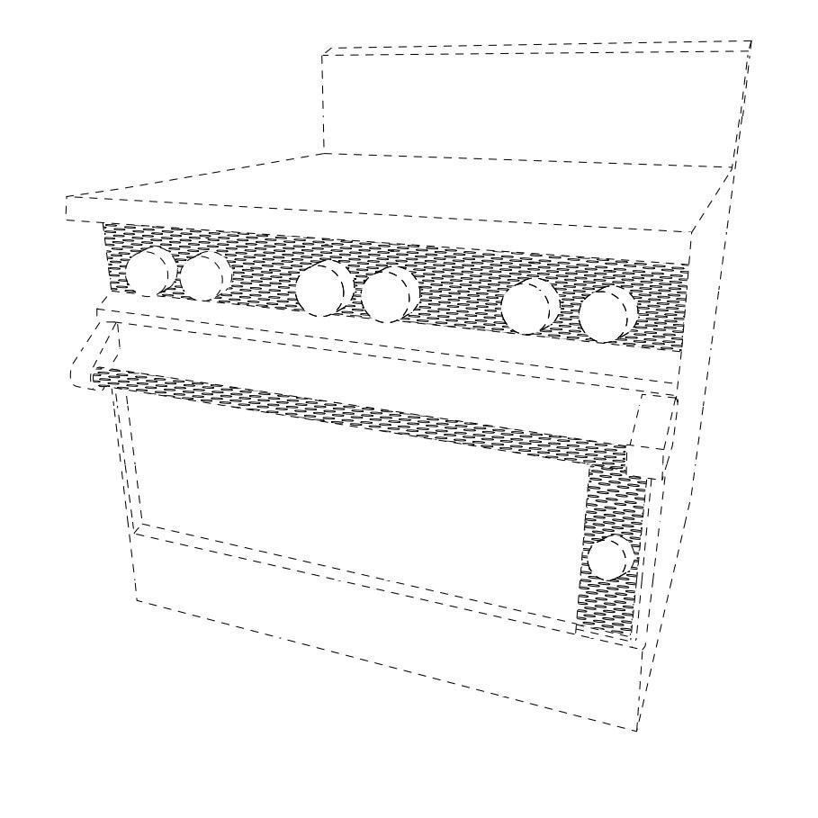
ABSTRACTA cooking range comprises: a frame having an upper rim surrounding an upper opening of a cavity; a pan coupled to the frame, the pan extending downward into the upper opening of the cavity, the pan having an upper level and a lower level, the lower level being positioned vertically lower than the upper level, the pan further having one or more upward extending ridges that separate the upper level from the lower level, wherein the top-most portion of each of the ridges is positioned vertically higher than the upper level; and a plurality of heat sources, wherein the first heat source is configured to provide a higher maximum thermal output than each of the second, third, and fourth heat sources, wherein the maximum thermal output of the first heat source is at least about 26,000 British thermal units (BTUs), and wherein the maximum thermal output of each of the second, third and fourth heat sources is at least about 18,000 BTUs.Date Recue/Date Received 2020-04-21
According to one example, a cooking vessel support grate includes a grate with at least two downward extending legs, with each leg having a lower surface. The cooking vessel support grate further includes an upward extending cavity disposed on the lower surface of each of the legs, and an elastic member attached to each of the legs. The elastic member has an upper portion that at least partially fills the cavity of the respective leg. The elastic member further has a lower portion that projects downward from the lower surface of the respective leg and that covers the surface area of the lower surface of the respective leg.
According to one embodiment, a rack includes a pair of spaced apart inverted U shaped brackets. Each bracket has a top portion coupled in-between a rear leg and a front leg and forming a gap in-between the rear leg and the front leg. The top portion, the rear leg, and front leg of each bracket are disposed in a first plane. The rack further includes one or more horizontal coupling members coupled in-between the pair of brackets. The horizontal coupling members and the front leg of each bracket are disposed in a second plane that is orthogonal to the first plane. The rack also includes one or more first horizontal supporting members coupled to and extending outward from a first bracket of the pair of brackets. The first horizontal supporting members are disposed in a third plane that is orthogonal to the first and second planes.
F24C 15/16 - Shelves, racks or trays inside ovensSupports therefor
F24C 1/14 - Radiation heating stoves or ranges, with additional provision for convection heating
A47B 57/14 - Cabinets, racks or shelf units, characterised by features for adjusting shelves or partitions with means for adjusting the height of the shelves consisting of side walls of the ladder type with hooks on the shelves to engage the rungs of the ladder
A grill or BBQ appliance that is generally intended for outdoor use has a pivoting hood disposed in hinged connection with a grill body, both of which are raised above a firebox that receives a food support grate including a set of food support modules. A gas burner assembly including a set of modular trellis burners may be positioned along the lower end of the firebox. A set of radiant tray modules may be correspondingly positioned between food support modules and burners. Branches of burner trellises may be spaced apart in distances corresponding to locations of an array of tiles grasped by the radiant tile module.
A grill or BBQ appliance that is generally intended for outdoor use has a pivoting hood disposed in hinged connection with a grill body, both of which are raised above a firebox that receives a food support grate. The hood may include a counterbalance mechanism to stably position the hood through a range of open positions. The hood may further include an opening or closing assist to assist a user in opening or closing the hood.
A grill or BBQ appliance that is generally intended for outdoor use has a pivoting hood disposed in hinged connection with a grill body, both of which are raised above a firebox that receives a food support grate. The hood may include various double wall configurations or cavities configured to protect wiring or electrical components such as lights or sensors.
A grill or BBQ appliance that is generally intended for outdoor use has a pivoting hood disposed in hinged connection with a grill body, both of which are raised above a firebox that receives a food support grate. A downward facing IR burner may be housed in an upper portion of the grill above the food support grate.
A radiant tray system may be positioned between a burner and a grate of a cooking device. The system may include ceramic tiles and a housing having generally planar walls configured to house the tiles therebetween. The walls receive and grasp tiles between corresponding tile slots through each of the walls and thereby stably position the tile within the tile slots. The walls may also include vent ports for promoting flow of combustion gases through the housing. The housing may be symmetrical with respect to a common reference plane disposed between the walls to support selectively invertable use of the housing. Inversion of the housing after use in one orientation allows drippings to be pyrolized during continued use in the inverted orientation. The pyrolized drippings are readily scrapped or brushed from the walls and tiles.
A grill or BBQ appliance that is generally intended for outdoor use has a pivoting hood disposed in hinged connection with a grill body, both of which are raised above a firebox that receives a food support grate. The hood may include overhanging lights configured to provide optimal lighting through a range of hood positions. The hood may also be counterbalanced to stably position the hood through a range of open positions.
According to one example, a convection oven comprises a cooking chamber having a front door and a rear door opposing the front door; a combustion chamber disposed below at least a portion of the cooking chamber; a side flue conduit configured to direct hot air from the combustion chamber to the cooking chamber; and a side sub-chamber with a convection fan configured to re-circulate at least a portion of the hot air within the cooking chamber, in which the side sub-chamber is disposed adjacent a side of the cooking chamber that is orthogonal to the front and rear door.
According to one example, a convection oven comprises a cooking chamber having a front door and a rear door opposing the front door; a combustion chamber disposed below at least a portion of the cooking chamber; a side flue conduit configured to direct hot air from the combustion chamber to the cooking chamber; and a side sub-chamber with a convection fan configured to re-circulate at least a portion of the hot air within the cooking chamber, in which the side sub-chamber is disposed adjacent a side of the cooking chamber that is orthogonal to the front and rear door.
A grill or BBQ appliance that is generally intended for outdoor use has a pivoting hood disposed in hinged connection with a grill body, both of which are raised above a firebox that receives a food support grate. The hood may include a counterbalance mechanism to stably position the hood through a range of open positions. The hood may further include an opening or closing assist to assist a user in opening or closing the hood.
A door for a towel dispensing cabinet may be pivotable over an opening of a cavity. Frameworks may extend from a face of the door and define slots for stably receiving ends of a spindle assembly onto which a towel roll may be mounted. The frameworks may also include channels through which a shaft connecting the ends of the spindle assembly may be received to allow the spindle assembly to be received deeper into the slots. Towels may be dispensed from spindle assembly when stably received within the frameworks when the door is open. The door may be closed to position the spindle assembly within the cavity and seal the opening. The spindle assembly may also be removed from the frameworks for separate use when the door is open.
A door for a towel dispensing cabinet may be pivotable over an opening of a cavity. Frameworks may extend from a face of the door and define slots for stably receiving ends of a spindle assembly onto which a towel roll may be mounted. The frameworks may also include channels through which a shaft connecting the ends of the spindle assembly may be received to allow the spindle assembly to be received deeper into the slots. Towels may be dispensed from spindle assembly when stably received within the frameworks when the door is open. The door may be closed to position the spindle assembly within the cavity and seal the opening. The spindle assembly may also be removed from the frameworks for separate use when the door is open.
A radiant tray system may be positioned between a burner and a grate of a cooking device. The system may include ceramic tiles and a housing having generally planar walls configured to house the tiles therebetween. The walls receive and grasp tiles between corresponding tile slots through each of the walls and thereby stably position the tile within the tile slots. The walls may also include vent ports for promoting flow of combustion gases through the housing. The housing may be symmetrical with respect to a common reference plane disposed between the walls to support selectively invertable use of the housing. Inversion of the housing after use in one orientation allows drippings to be pyrolized during continued use in the inverted orientation. The pyrolized drippings are readily scrapped or brushed from the walls and tiles.
A grill or BBQ appliance that is generally intended for outdoor use has a pivoting hood disposed in hinged connection with a grill body, both of which are raised above a firebox that receives a food support grate including a set of food support modules. A gas burner assembly including a set of modular trellis burners may be positioned along the lower end of the firebox. A set of radiant tray modules may be correspondingly positioned between food support modules and burners. Branches of burner trellises may be spaced apart in distances corresponding to locations of an array of tiles grasped by the radiant tile module.
A grill or BBQ appliance that is generally intended for outdoor use has a pivoting hood disposed in hinged connection with a grill body, both of which are raised above a firebox that receives a food support grate. A downward facing IR burner may be housed in an upper portion of the grill above the food support grate.
A grill or BBQ appliance that is generally intended for outdoor use has a pivoting hood disposed in hinged connection with a grill body, both of which are raised above a firebox that receives a food support grate. The hood may include overhanging lights configured to provide optimal lighting through a range of hood positions. The hood may also be counterbalanced to stably position the hood through a range of open positions.
A grill or BBQ appliance that is generally intended for outdoor use has a pivoting hood disposed in hinged connection with a grill body, both of which are raised above a firebox that receives a food support grate. The hood may include various double wall configurations or cavities configured to protect wiring or electrical components such as lights or sensors.
A grill or BBQ appliance that is generally intended for outdoor use has a pivoting hood disposed in hinged connection with a grill body, both of which are raised above a firebox that receives a food support grate. The hood may include various double wall configurations or cavities configured to protect wiring or electrical components such as lights or sensors.
A grill or BBQ appliance that is generally intended for outdoor use has a pivoting hood disposed in hinged connection with a grill body, both of which are raised above a firebox that receives a food support grate. The hood may include overhanging lights configured to provide optimal lighting through a range of hood positions.
A radiant tray system may be positioned between a burner and a grate of a cooking device. The system may include ceramic tiles and a housing having generally planar walls configured to house the tiles therebetween. The walls receive and grasp tiles between corresponding tile slots through each of the walls and thereby stably position the tile within the tile slots. The walls may also include vent ports for promoting flow of combustion gases through the housing. The housing may be symmetrical with respect to a common reference plane disposed between the walls to support selectively invertable use of the housing. Inversion of the housing after use in one orientation allows drippings to be pyrolized during continued use in the inverted orientation. The pyrolized drippings are readily scrapped or brushed from the walls and tiles.
An oven system may include a cooking chamber, a combustion chamber, and a flue. The flue may be arranged to route a first portion of the combustion gas produced in the combustion chamber into the cooking chamber and route a second portion of the combustion gas along a route that bypasses the cooking chamber. The flue may also be arranged to collect the first portion of the combustion gas from the cooking chamber and to exhaust both the first portion and the second portion of the combustion gas from the oven system.
B23P 19/00 - Machines for simply fitting together or separating metal parts or objects, or metal and non-metal parts, whether or not involving some deformationTools or devices therefor so far as not provided for in other classes
According to one embodiment, a food support grate includes a plurality of slats. Each of the slats has an upper cooking surface having an upper apex; a lower cooking surface having a lower apex; a rear side; and a front side. The food support grate further includes a plurality of bridges that each couple two or more adjacent slats to each other. The upper apexes define an upper plane and the lower apexes define a lower plane. The rear sides and the front sides each have a portion positioned at an oblique angle with respect to one of the upper and lower planes. The upper apex of each of the slats has a first radius of curvature, and the lower apex of each of the slats has a second radius of curvature. The first radius of curvature is smaller than the second radius of curvature.
According to one embodiment, a cooking unit includes a rear housing, a heating chamber coupled to the rear housing, and one or more vertical tracks coupled to the rear housing. The cooking unit further includes a support shelf coupled to the vertical tracks, and operable to be moved vertically along the vertical tracks. The cooking unit also includes a sliding tray coupled to the support shelf, and operable to be moved horizontally with respect to the rear housing. The cooking unit further includes a handle coupled to a front surface of the sliding tray, and an actuator positioned adjacent to the handle so as to allow both the handle to be grasped and the actuator engaged by a single hand of a user. The actuator is operable to unlock the horizontal support shelf so as to allow the horizontal support shelf to be moved vertically along the vertical tracks.
An oven system may include a cooking chamber, a combustion chamber, and a flue. The flue may be arranged to route a first portion of the combustion gas produced in the combustion chamber into the cooking chamber and route a second portion of the combustion gas along a route that bypasses the cooking chamber. The flue may also be arranged to collect the first portion of the combustion gas from the cooking chamber and to exhaust both the first portion and the second portion of the combustion gas from the oven system.
According to one embodiment, a food support grate includes a plurality of slats. Each of the slats has an upper cooking surface having an upper apex; a lower cooking surface having a lower apex; a rear side; and a front side. The food support grate further includes a plurality of bridges that each couple two or more adjacent slats to each other. The upper apexes define an upper plane and the lower apexes define a lower plane. The rear sides and the front sides each have a portion positioned at an oblique angle with respect to one of the upper and lower planes. The upper apex of each of the slats has a first radius of curvature, and the lower apex of each of the slats has a second radius of curvature. The first radius of curvature is smaller than the second radius of curvature.
According to one embodiment, a cooking unit includes a rear housing, a heating chamber coupled to the rear housing, and one or more vertical tracks coupled to the rear housing. The cooking unit further includes a support shelf coupled to the vertical tracks, and operable to be moved vertically along the vertical tracks. The cooking unit also includes a sliding tray coupled to the support shelf, and operable to be moved horizontally with respect to the rear housing. The cooking unit further includes a handle coupled to a front surface of the sliding tray, and an actuator positioned adjacent to the handle so as to allow both the handle to be grasped and the actuator engaged by a single hand of a user. The actuator is operable to unlock the horizontal support shelf so as to allow the horizontal support shelf to be moved vertically along the vertical tracks.
According to one embodiment, an oven includes an oven chamber operable to be heated and having a front opening. The oven further includes a frame coupled to and at least partially surrounding the oven chamber. The oven further includes a door operable to seal the front opening of the oven chamber, and a pair of hinges pivotally coupling the door to the frame. Each hinge is positioned on opposing sides of the oven chamber. The oven further includes a pair counterweights that are each coupled to the rear portion of a respective hinge, and a pair of dampers. Each damper is coupled to the frame and operable to resist movement of the door in a single direction opposite that of the other damper.
According to one embodiment, a rack includes a pair of spaced apart inverted U shaped brackets. Each bracket has a top portion coupled in-between a rear leg and a front leg and forming a gap in-between the rear leg and the front leg. The top portion, the rear leg, and front leg of each bracket are disposed in a first plane. The rack further includes one or more horizontal coupling members coupled in-between the pair of brackets. The horizontal coupling members and the front leg of each bracket are disposed in a second plane that is orthogonal to the first plane. The rack also includes one or more first horizontal supporting members coupled to and extending outward from a first bracket of the pair of brackets. The first horizontal supporting members are disposed in a third plane that is orthogonal to the first and second planes.
F24C 15/32 - Arrangements of ducts for hot gases, e.g. in or around baking ovens
F24C 15/16 - Shelves, racks or trays inside ovensSupports therefor
F24C 1/14 - Radiation heating stoves or ranges, with additional provision for convection heating
A47B 57/14 - Cabinets, racks or shelf units, characterised by features for adjusting shelves or partitions with means for adjusting the height of the shelves consisting of side walls of the ladder type with hooks on the shelves to engage the rungs of the ladder
A cooking range (100) includes a combustion chamber (110) surrounded by sidewalls that extend upward to an upper rim (113), a gas burner (120) positioned at the bottom (111) of the combustion chamber (110), and a platen (130) positioned on the upper rim (113). The platen (130) has an opening above the gas burner (120) with a first flange. A removable outer plate (140) is positionable on the first flange. The removable outer plate (140) can include a second flange, and a removable inner plate (150) positioned on the second flange. The removable outer plate (140) can be configured to increase the thermal resistance between the removable inner plate (150) and the platen (130) by having at least one of a different composition, thickness, and limited contact area than or with the platen. An enclosure (160) can surround the gas burner (120) and can cause preferential heating of the removable inner plate (150). First and second gas burners can be included, and the second gas burner can be a linear flame source.
A cooking range (100) includes a combustion chamber (110) surrounded by sidewalls that extend upward to an upper rim (113), a gas burner (120) positioned at the bottom (111) of the combustion chamber (110), and a platen (130) positioned on the upper rim (113). The platen (130) has an opening above the gas burner (120) with a first flange. A removable outer plate (140) is positionable on the first flange. The removable outer plate (140) can include a second flange, and a removable inner plate (150) positioned on the second flange. The removable outer plate (140) can be configured to increase the thermal resistance between the removable inner plate (150) and the platen (130) by having at least one of a different composition, thickness, and limited contact area than or with the platen. An enclosure (160) can surround the gas burner (120) and can cause preferential heating of the removable inner plate (150). First and second gas burners can be included, and the second gas burner can be a linear flame source.
According to one embodiment, a range for cooking includes a combustion chamber having a bottom surrounded by sidewalls that extend upward to an upper rim, a gas burner positioned at the bottom, and a platen positioned on the upper rim. The platen has an opening above the gas burner with a first flange. The range further includes a removable outer plate positioned on the first flange. The removable outer plate has an opening above the gas burner with a second flange. The range further includes a removable inner plate positioned on the second flange. The removable inner plate is circular and is made of cast iron. The removable outer plate is configured to increase the thermal resistance between the removable inner plate and the platen by having at least one of a different composition, thickness, and limited contact area than or with the platen.
According to one embodiment, a range for cooking includes a combustion chamber having a bottom surrounded by sidewalls that extend upward to an upper rim. The range further includes at least one gas burner positioned at the bottom of the combustion chamber, and a platen positioned on the upper rim. The platen has an interior opening above one of the at least one gas burner with a first flange. The range further includes at least one removable outer plate positioned on the first flange of the platen, and an enclosure disposed to surround the gas burner and that is operative to cause preferential heating of the removable inner plate by radiation from a flame at the one of the at least one gas burner and radiation from the enclosure.
According to one embodiment, a range for cooking includes at least one combustion chamber having a bottom surrounded by sidewalls that extend upward to an upper rim. The range further includes first and second gas burners positioned at the bottom of the at least one combustion chamber, and a first platen positioned on a first portion of the upper rim. The first platen has an interior opening above the first gas burner with a first flange. The range further includes a first removable plate positioned on the first flange. The first removable plate has an interior opening above the first gas burner with a second flange. The range further includes a removable inner plate positioned on the second flange. The range further includes a second platen positioned over a remaining portion of the upper rim. The second gas burner is a linear flame source positioned under the second platen.
According to one embodiment, an oven includes an oven chamber operable to be heated and having a front opening. The oven further includes a frame coupled to and at least partially surrounding the oven chamber. The oven further includes a door operable to seal the front opening of the oven chamber, and a pair of hinges pivotally coupling the door to the frame. Each hinge is positioned on opposing sides of the oven chamber. The oven further includes a pair of counterweights that are each coupled to the rear portion of a respective hinge, and a pair of dampers. Each damper is coupled to the frame and operable to resist movement of the door in a single direction opposite that of the other damper.
According to one embodiment, a rack includes a pair of spaced apart inverted U shaped brackets. Each bracket has a top portion coupled in-between a rear leg and a front leg and forming a gap in-between the rear leg and the front leg. The top portion, the rear leg, and front leg of each bracket are disposed in a first plane. The rack further includes one or more horizontal coupling members coupled in-between the pair of brackets. The horizontal coupling members and the front leg of each bracket are disposed in a second plane that is orthogonal to the first plane. The rack also includes one or more first horizontal supporting members coupled to and extending outward from a first bracket of the pair of brackets. The first horizontal supporting members are disposed in a third plane that is orthogonal to the first and second planes.