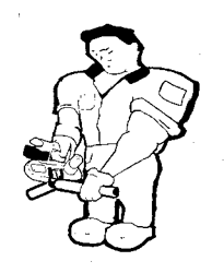
A control assembly for a material dispenser includes a plunger movably located within a bore of the assembly, the plunger having first and second ends, the first end having an abutment for moveably retaining the plunger within the bore and the second end for engaging a switch during operation of the material dispenser to cease operation. A biasing member located within the bore, the biasing member engaging the first end of the plunger, the biasing member allowing for the manual movement of the plunger without harm to the switch of the material dispenser during use.
B05B 12/00 - Arrangements for controlling deliveryArrangements for controlling the spray area
B05B 12/02 - Arrangements for controlling deliveryArrangements for controlling the spray area for controlling time, or sequence, of delivery
H02P 3/06 - Arrangements for stopping or slowing electric motors, generators, or dynamo-electric converters for stopping or slowing an individual dynamo-electric motor or dynamo-electric converter
B05C 17/01 - Hand tools or apparatus using hand-held tools, for applying liquids or other fluent materials to, for spreading applied liquids or other fluent materials on, or for partially removing applied liquids or other fluent materials from, surfaces for discharging material through an outlet orifice by pressure with mechanically or electrically actuated piston or the like
B05C 11/10 - Storage, supply or control of liquid or other fluent materialRecovery of excess liquid or other fluent material
B05C 17/005 - Hand tools or apparatus using hand-held tools, for applying liquids or other fluent materials to, for spreading applied liquids or other fluent materials on, or for partially removing applied liquids or other fluent materials from, surfaces for discharging material through an outlet orifice by pressure
A trigger assembly can be used to activate a motor controller to cause a motorized device to respond in a certain manner. For example, when the motorized device is a power tool, based on a number of pulls of the trigger, the motor controller can run the power tool in a forward direction or a reverse direction. A power tool running in the forward direction can receive a tap of the trigger. A timer can be started upon detecting the pull of the trigger. Another tap of the trigger can be detected within a time period determined based on the timer. The power tool can be forced to perform a reverse operation when the other tap f the trigger is within the time period.
B65D 83/00 - Containers or packages with special means for dispensing contents
B05B 12/02 - Arrangements for controlling deliveryArrangements for controlling the spray area for controlling time, or sequence, of delivery
B05B 12/00 - Arrangements for controlling deliveryArrangements for controlling the spray area
H02P 3/06 - Arrangements for stopping or slowing electric motors, generators, or dynamo-electric converters for stopping or slowing an individual dynamo-electric motor or dynamo-electric converter
B05C 17/01 - Hand tools or apparatus using hand-held tools, for applying liquids or other fluent materials to, for spreading applied liquids or other fluent materials on, or for partially removing applied liquids or other fluent materials from, surfaces for discharging material through an outlet orifice by pressure with mechanically or electrically actuated piston or the like
B05C 11/10 - Storage, supply or control of liquid or other fluent materialRecovery of excess liquid or other fluent material
B05C 17/005 - Hand tools or apparatus using hand-held tools, for applying liquids or other fluent materials to, for spreading applied liquids or other fluent materials on, or for partially removing applied liquids or other fluent materials from, surfaces for discharging material through an outlet orifice by pressure
4.
BATTERY POWERED DISPENSER FOR ONE AND TWO COMPONENT FOILS AND CARTRIDGES
An assembly for a dispenser includes a front plate having a first tube aperture configured for securably receiving a tube within the aperture, the tube being configured to receive a container having a flowable material; a release assembly disposed on the front plate having first and second members hingingly movable about a hinge portion on each of the first and second members for partially covering the first tube aperture when the first and second members are in a closed position and for uncovering the aperture when the first and second members are in an open position. A combination includes a dispenser and the assembly releasably secured to the discharge gun. A kit includes a container having a flowable material; the dispenser having plunger; and the assembly releasably secured to the discharge gun.
B05C 5/00 - Apparatus in which liquid or other fluent material is projected, poured or allowed to flow on to the surface of the work
B05C 17/00 - Hand tools or apparatus using hand-held tools, for applying liquids or other fluent materials to, for spreading applied liquids or other fluent materials on, or for partially removing applied liquids or other fluent materials from, surfaces
A material dispensing assembly (100) and method of operation for converting a portable cartridge dispensing tool to a bag-type dispensing tool is provided in which the assembly includes a single piece piston (110) for advancing material though a material housing (104). The single piece piston (110) includes a substantially square-shaped receptacle (140). The assembly further includes a square shaped drive rack (112) for attaching to the piston (110) at the substantially square-shaped receptacle (140) at a connection end (128). The drive rack (112) further includes a plurality of teeth (142) located thereon. The assembly (100) further has a support (127) with a substantially square profile for receiving and supporting the drive rack (112) during operation such that the construct of the drive rack and piston (110) are prevented from rotating during operation.
B05C 17/005 - Hand tools or apparatus using hand-held tools, for applying liquids or other fluent materials to, for spreading applied liquids or other fluent materials on, or for partially removing applied liquids or other fluent materials from, surfaces for discharging material through an outlet orifice by pressure
G01F 11/02 - Apparatus requiring external operation adapted at each repeated and identical operation to measure and separate a predetermined volume of fluid or fluent solid material from a supply or container, without regard to weight, and to deliver it with measuring chambers which expand or contract during measurement
B65D 83/00 - Containers or packages with special means for dispensing contents
A material dispensing assembly (100) and method of operation for converting a portable cartridge dispensing tool to a bag-type dispensing tool is provided in which the assembly includes a single piece piston (110) for advancing material though a material housing (104). The single piece piston (110) includes a substantially square-shaped receptacle (140). The assembly further includes a square shaped drive rack (112) for attaching to the piston (110) at the substantially square-shaped receptacle (140) at a connection end (128). The drive rack (112) further includes a plurality of teeth (142) located thereon. The assembly (100) further has a support (127) with a substantially square profile for receiving and supporting the drive rack (112) during operation such that the construct of the drive rack and piston (110) are prevented from rotating during operation.
B67D 7/60 - Arrangements of pumps manually operable
B65D 83/00 - Containers or packages with special means for dispensing contents
G01F 11/02 - Apparatus requiring external operation adapted at each repeated and identical operation to measure and separate a predetermined volume of fluid or fluent solid material from a supply or container, without regard to weight, and to deliver it with measuring chambers which expand or contract during measurement
10.
Powered dispensing tool and method for controlling same
An apparatus and method for monitoring and controlling motor current during a dispensing of material from a dispensing tool (10) is provided, including a method for measuring the motor current of the dispensing tool during operation through a motor controller (U2). The method further includes sending a feedback signal from the motor controller (U2) relating to the measured motor current to an input of a microcontroller (U1) that is adapted to a dispensing tool (10). The feedback signal is compared to a prescribed threshold and the motor current is conditioned based on the comparing of the feedback signal to the prescribed threshold.
B05C 17/01 - Hand tools or apparatus using hand-held tools, for applying liquids or other fluent materials to, for spreading applied liquids or other fluent materials on, or for partially removing applied liquids or other fluent materials from, surfaces for discharging material through an outlet orifice by pressure with mechanically or electrically actuated piston or the like
An apparatus for dispensing material is provided having a body portion and housing for supporting cartridges filled with materials for dispensing. The housing includes a dispensing end, an attachment end, and an elongated opening for receiving the cartridges. The apparatus further comprises an attachment assembly located at an end of the body portion for attaching the housing to the body portion. The attachment assembly includes a first set of threads located about the perimeter of the attachment assembly. A second set of threads are located about the perimeter of the attachment end of the housing for engaging the first set of threads, forming a threaded connection and attaching the housing to the body portion.
An apparatus and method for monitoring and controlling motor current during a dispensing of material from a dispensing tool (10) is provided, including a method for measuring the motor current of the dispensing tool during operation through a motor controller (U2). The method further includes sending a feedback signal from the motor controller (U2) relating to the measured motor current to an input of a microcontroller (U1) that is adapted to a dispensing tool (10). The feedback signal is compared to a prescribed threshold and the motor current is conditioned based on the comparing of the feedback signal to the prescribed threshold.
B05C 17/01 - Hand tools or apparatus using hand-held tools, for applying liquids or other fluent materials to, for spreading applied liquids or other fluent materials on, or for partially removing applied liquids or other fluent materials from, surfaces for discharging material through an outlet orifice by pressure with mechanically or electrically actuated piston or the like
A material dispensing assembly (100) and method of operation is disclosed for converting a portable cartridge dispensing tool to a bag-type dispensing tool. The assembly comprises a single piece piston (110) for advancing material though a material housing (104), the single piece piston (110) includes a substantially square-shaped receptacle (140). The assembly further comprises a square shaped drive rack (112) for attaching to the piston (110) at the substantially square-shaped receptacle (140) at a connection end (128). The drive rack (112) further comprises a plurality of teeth (142) located thereon. The assembly (100) further has a support (127) with a substantially square profile for receiving and supporting the drive rack (112) during operation such that the construct of the drive rack and piston (110) are prevented from rotating during operation.
A material dispensing assembly (100) and method of operation is disclosed for converting a portable cartridge dispensing tool to a bag-type dispensing tool. The assembly comprises a single piece piston (110) for advancing material though a material housing (104), the single piece piston (110) includes a substantially square-shaped receptacle (140). The assembly further comprises a square shaped drive rack (112) for attaching to the piston (110) at the substantially square-shaped receptacle (140) at a connection end (128). The drive rack (112) further comprises a plurality of teeth (142) located thereon. The assembly (100) further has a support (127) with a substantially square profile for receiving and supporting the drive rack (112) during operation such that the construct of the drive rack and piston (110) are prevented from rotating during operation.
B65D 35/28 - Pliable tubular containers adapted to be permanently deformed to expel contents, e.g. collapsible tubes for toothpaste or other plastic or semi-liquid materialHolders therefor with auxiliary devices for expelling contents
B65D 88/62 - Large containers characterised by means facilitating filling or emptying by displacement of walls of internal walls the walls being deformable
B65D 88/60 - Large containers characterised by means facilitating filling or emptying by displacement of walls of internal walls
B65D 88/58 - Large containers characterised by means facilitating filling or emptying by displacement of walls
An apparatus for dispensing material is provided having a body portion and housing for supporting cartridges filled with materials for dispensing. The housing includes a dispensing end, an attachment end, and an elongated opening for receiving the cartridges. The apparatus further comprises an attachment assembly located at an end of the body portion for attaching the housing to the body portion. The attachment assembly includes a first set of threads located about the perimeter of the attachment assembly. A second set of threads are located about the penmeter of the attachment end of the housing for engaging the first set of threads, forming a threaded connection and attaching the housing to the body portion.
An apparatus for dispensing material is provided having a body portion and housing for supporting cartridges filled with materials for dispensing. The housing includes a dispensing end, an attachment end, and an elongated opening for receiving the cartridges. The apparatus further comprises an attachment assembly located at an end of the body portion for attaching the housing to the body portion. The attachment assembly includes a first set of threads located about the perimeter of the attachment assembly. A second set of threads are located about the perimeter of the attachment end of the housing for engaging the first set of threads, forming a threaded connection and attaching the housing to the body portion.
A piston assembly for use in a viscous material dispenser is disclosed. The assembly has a main body with an axial bore for receipt of a push rod. The body has a face including an annular recess and an endless lip surrounding the recess. A camming washer is disposed at least in part in the recess. The washer includes a perimeteral camming surface engageable with the lip. The body and washer are connected together for limited relative axial movement when the piston assembly is advanced against material in a cartridge to dispense such material. The relative movement is effective to cause the camming surface to force the lip outwardly into tight engagement with a wall of such a cartridge.