The present technology relates to a poultry-processing machine designed to streamline and enhance the efficiency of poultry-processing operations. In some embodiments, the machine includes a chassis, a processing tub supported on the chassis, a motor mounted on the chassis or the processing tub, wheels rotatably supported on legs attached to or integral with the chassis, a handle extending upwardly from the chassis optionally above the top surface of the processing tub, a mounting plate supported on arms of the handle, and a control switch positioned on the mounting plate in electrical communication or (other communication) with the motor. In some embodiments, the handle is a multi-piece handle that can be separated into two or more pieces down to reduce the profile of the machine, which facilitates efficient packaging and storage of the machine. These features facilitate easier use and transport of the machine.
A cutting head body for an agricultural machine, such as a mower or a trimmer, is configured to receive a cutting line for cutting weeds, grass, or other materials. The cutting head body includes an inlet area having a cavity with a node location configured to receive a node of a cutting line, and an outlet area having a cavity configured to open to an exterior of the cutting head body. The cutting head body may include a first passageway connecting the inlet area to the outlet area and a second passageway connecting the inlet area to the outlet area. The cutting head body is rotatable about a rotational axis to move the cutting line. In some embodiments, the cutting head body is fixed to a rotatable shaft. In some embodiments, the cutting head body rotates about a fixed shaft.
A01D 34/84 - MowersMowing apparatus of harvesters specially adapted for particular purposes for edges of lawns or fields, e.g. for mowing close to trees or walls
A01D 34/90 - MowersMowing apparatus of harvesters specially adapted for particular purposes for carrying by the operator
3.
PORTABLE LADDER AND STAND SYSTEMS AND KNEE SUPPORTS
A knee support system supports a user's knees when the user is in an elevated position along a support structure, such as when the user is suspended in a harness from the support structure (e.g., saddle hunting). The knee support system may include a bracket attachable to the support structure via one or more blade portions for engaging the support structure and a single rope cinching around the support structure and passing through slots on the bracket that hold the rope with frictional engagement. A frame with optional knee pads may slide on and off the bracket. The frame may include one or more hooks that engage a blade portion of the bracket. The frame may also be removably attachable to a seat post of the platform assembly as part of a portable and modular stand system.
A portable ladder and stand system includes a platform assembly, a plurality of nestable ladder portions, a pack portion, and a carrying assembly. A central compartment of the pack portion may be positioned in the nested ladder portions to carry the ladder portions. The pack portion may be attached to the platform assembly and the carrying assembly for a user to carry the system for transport to a deployment location (e.g., via shoulder straps), where the platform assembly and one or more of the nestable ladder portions may be attached to a support structure for a user to ascend the support structure and stand or sit on the platform assembly. The pack portion may be used separately from the remainder of the system.
A restraint device for harvesting birds may include a flexible sheet configurable between a first configuration in which the flexible sheet is flat, a second configuration in which the flexible sheet is formed into a conical shape having a first interior volume, an upper opening, and a lower opening smaller than the upper opening, and a third configuration in which the flexible sheet is formed into a conical shape having a second interior volume that is different from the first interior volume. The restraint device may include two or more elongated openings positioned to receive corresponding hook elements to secure the flexible sheet in the second or third configuration.
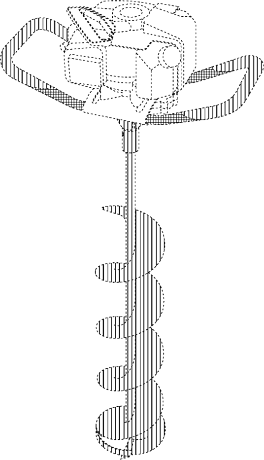
An auger system may include a powerhead, a bit, and an anchoring device. A collar on the bit may be attachable to a rotatable output shaft of the powerhead with a coupler that is positionable around the collar. The collar may include a passageway that does not intersect the rotation axis of the output shaft. The coupler may have a pin that is positionable to extend into the passageway to engage part of the output shaft to resist removal of the bit from the output shaft. The anchoring device may have a tube that is positionable to rest in slots between two lobes extending from a frame of the powerhead. A pintle assembly may pass through the tube and the lobes to rotatably mount the anchoring device on the frame. A toggle and a spring in the pintle assembly may keep the pintle assembly in position.
A cutting head body for an agricultural machine, such as a mower or a trimmer, is configured to receive a cutting line for cutting weeds, grass, or other materials. The cutting head body includes an inlet area having a cavity with a node location configured to receive a node of a cutting line, and an outlet area having a cavity configured to open to an exterior of the cutting head body. The cutting head body may include a first passageway connecting the inlet area to the outlet area and a second passageway connecting the inlet area to the outlet area. The cutting head body is rotatable about a rotational axis to move the cutting line. In some embodiments, the cutting head body is fixed to a rotatable shaft. In some embodiments, the cutting head body rotates about a fixed shaft.
A01D 34/84 - MowersMowing apparatus of harvesters specially adapted for particular purposes for edges of lawns or fields, e.g. for mowing close to trees or walls
A01D 34/90 - MowersMowing apparatus of harvesters specially adapted for particular purposes for carrying by the operator
A driveline assembly for equipment, such as a tiller, includes a pair of counter-rotating bevel gears supported on a wheel shaft and rotatable relative to the wheel shaft. The driveline assembly includes a first slider gear movable between a first position in which the first slider gear is engaged with a first bevel gear of the pair of bevel gears, and a second position in which the first slider gear is engaged with a second bevel gear of the pair of bevel gears. When the first slider gear is engaged with the first bevel gear, the first bevel gear becomes operatively connected to a rotatable tine shaft to rotate tines in a first direction. When the first slider gear is engaged with the second bevel gear, the second bevel gear becomes operatively connected to the rotatable tine shaft to rotate the tines in a second direction opposite the first direction.
A01B 33/08 - ToolsDetails, e.g. adaptations of transmissions or gearings
A01B 33/02 - Tilling implements with rotary driven tools with tools on horizontal shaft transverse to direction of travel
F16H 1/06 - Toothed gearings for conveying rotary motion without gears having orbital motion involving only two intermeshing members with parallel axes
A portable shelter includes a frame structure with a plurality of pole structures. In some embodiments, a pole structure includes telescopically movable pole portions and a spring-biasing mechanism configured to bias one pole portion away from the other. In some embodiments, a center hub structure of the portable shelter includes a locking mechanism for engaging one of the pole portions to interfere with telescopic movement of the pole structure. In some embodiments, a pole structure includes a flexible portion attached to a first rigid portion, and a second rigid portion that is movable relative to the first rigid portion. The second rigid portion is pivotable or telescopically movable between a first position in which the second rigid portion overlaps the first rigid portion such that the flexible portion is free to flex, and a second position in which the second rigid portion overlaps and restrains the flexible portion.
A stowable and deployable shelter may include a frame structure with a first support arch pivotably attached to a base at a pair of pivot points, and a second support arch pivotably attached to the first support arch via a pair of slidable hinges. The slidable hinges are positioned to translate along the first support arch toward and away from the pair of pivot points. In some embodiments, at least one of the slidable hinges includes a locking mechanism for releasably locking the at least one slidable hinge at a selected location along the first support arch. In some embodiments, the hinges may be fixed instead of being slidable. The support arches support a fabric shell to form an interior of the shelter. The base may include a sled container having runners for sliding through snow or across terrain.
A cordless drill powered log splitter. The cordless drill powered log splitter includes a body and one or more rails, the one or more rails configured to support a piece of wood during a splitting operation. The cordless drill powered log splitter also includes a splitting wedge mounted on the body and a contact member, the contact member configured to press the piece of wood against the splitting wedge during the splitting operation. The cordless drill powered log splitter further includes a transmission, the transmission configured to move the contact member relative to the body and connect to a cordless drill, where the cordless drill provides the power to the transmission.
A shelter system may include a roof structure with a hub structure, a plurality of roof pole structures connectable to the hub structure and positionable to extend outwardly from the hub structure, and a fabric panel configured to be at least partially suspended from the roof pole structures. The fabric panel may include a reversible pocket. The roof structure is configurable between a stowed configuration and a deployed configuration. When the roof structure is in the stowed configuration, the hub structure and at least a portion of each roof pole structure may be positioned in the reversible pocket. When the roof structure is in the deployed configuration, the hub structure may be positioned above or outside of the reversible pocket. The shelter system may further include a rainfly that is positionable over the fabric panel with a gap between the rainfly and the fabric panel for airflow.
A tree stand includes an activity rail assembly rotatably attached to a chair. The activity rail assembly is rotatable among a first stowed position in which the activity rail assembly is oriented upright, a second stowed position in which the activity rail assembly is oriented downwardly, and one or more deployed positions between the first stowed position and the second stowed position. The activity rail assembly is extendable and retractable between a first position and a second position, wherein when the activity rail assembly is in the first position, a horizontal activity rail portion is closer to the chair than when the activity rail assembly is in the second position. The tree stand may further include a platform to support the chair, and, optionally, a ladder portion to support the platform.
A shelter includes a frame structure with a plurality of pole structures. In some embodiments, a telescoping pole structure includes a shell pole portion extending along a longitudinal axis, a sleeve fixed to the shell pole portion, and an inner pole portion extending along the longitudinal axis and positioned at least partially within the shell pole portion and at least partially within the sleeve. The inner pole portion slides telescopically relative to the shell pole portion. The sleeve may be rotatable and it may include an engagement surface having one or more surface positions for contacting a detent element attached to the inner pole portion. Contact between the detent element and each of the one or more surface positions prevents the inner pole portion from moving telescopically into the shell pole portion. Turning the sleeve may extend or retract the telescoping pole structure.
A shelter system may include a roof structure with a hub structure, a plurality of roof pole structures connectable to the hub structure and positionable to extend outwardly from the hub structure, and a fabric panel configured to be at least partially suspended from the roof pole structures. The fabric panel may include a reversible pocket. The roof structure is configurable between a stowed configuration and a deployed configuration. When the roof structure is in the stowed configuration, the hub structure and at least a portion of each roof pole structure may be positioned in the reversible pocket. When the roof structure is in the deployed configuration, the hub structure may be positioned above or outside of the reversible pocket. The shelter system may further include a rainfly that is positionable over the fabric panel with a gap between the rainfly and the fabric panel for airflow.
A portable shelter includes a frame structure with a plurality of pole structures. In some embodiments, a pole structure includes telescopically movable pole portions and a spring-biasing mechanism configured to bias one pole portion away from the other. In some embodiments, a center hub structure of the portable shelter includes a locking mechanism for engaging one of the pole portions to interfere with telescopic movement of the pole structure. In some embodiments, a pole structure includes a flexible portion attached to a first rigid portion, and a second rigid portion that is movable relative to the first rigid portion. The second rigid portion is pivotable or telescopically movable between a first position in which the second rigid portion overlaps the first rigid portion such that the flexible portion is free to flex, and a second position in which the second rigid portion overlaps and restrains the flexible portion.
A stowable and deployable shelter may include a frame structure with a first support arch pivotably attached to a base at a pair of pivot points, and a second support arch pivotably attached to the first support arch via a pair of slidable hinges. The slidable hinges are positioned to translate along the first support arch toward and away from the pair of pivot points. In some embodiments, at least one of the slidable hinges includes a locking mechanism for releasably locking the at least one slidable hinge at a selected location along the first support arch. In some embodiments, the hinges may be fixed instead of being slidable. The support arches support a fabric shell to form an interior of the shelter. The base may include a sled container having runners for sliding through snow or across terrain.
A ladder stand includes a ladder portion, a platform on the ladder portion, and a plurality of support straps to hold the ladder stand against a support structure. The plurality of support straps may include upper support straps that are each connected to the ladder stand, wrap partially around the tree, and connect to each other with a connecting device, to position the tree between the ladder stand and the straps. The platform may include a blade element positioned to press against the tree when the support straps are tightened against the tree. A method of installing a ladder stand may include connecting ends of the upper support straps to each other after passing the ends around an obstruction on the tree. A user may pull on other ends of the straps to draw the straps upward along the tree until they are approximately level with the blade element.
A tree stand includes an activity rail assembly rotatably attached to a chair. The activity rail assembly is rotatable among a first stowed position in which the activity rail assembly is oriented upright, a second stowed position in which the activity rail assembly is oriented downwardly, and one or more deployed positions between the first stowed position and the second stowed position. The activity rail assembly is extendable and retractable between a first position and a second position, wherein when the activity rail assembly is in the first position, a horizontal activity rail portion is closer to the chair than when the activity rail assembly is in the second position. The tree stand may further include a platform to support the chair, and, optionally, a ladder portion to support the platform.
A stowable and deployable shelter may include a frame structure with a first support arch pivotably attached to a base at a pair of pivot points, and a second support arch pivotably attached to the first support arch via a pair of slidable hinges. The slidable hinges are positioned to translate along the first support arch toward and away from the pair of pivot points. In some embodiments, at least one of the slidable hinges includes a locking mechanism for releasably locking the at least one slidable hinge at a selected location along the first support arch. In some embodiments, the hinges may be fixed instead of being slidable. The support arches support a fabric shell to form an interior of the shelter. The base may include a sled container having runners for sliding through snow or across terrain.
A portable shelter includes a frame structure with a plurality of pole structures. In some embodiments, a pole structure includes telescopically movable pole portions and a spring-biasing mechanism configured to bias one pole portion away from the other. In some embodiments, a center hub structure of the portable shelter includes a locking mechanism for engaging one of the pole portions to interfere with telescopic movement of the pole structure. In some embodiments, a pole structure includes a flexible portion attached to a first rigid portion, and a second rigid portion that is movable relative to the first rigid portion. The second rigid portion is pivotable or telescopically movable between a first position in which the second rigid portion overlaps the first rigid portion such that the flexible portion is free to flex, and a second position in which the second rigid portion overlaps and restrains the flexible portion.
A portable shelter includes a frame structure with a plurality of pole structures. In some embodiments, a pole structure includes telescopically movable pole portions and a spring-biasing mechanism configured to bias one pole portion away from the other. In some embodiments, a center hub structure of the portable shelter includes a locking mechanism for engaging one of the pole portions to interfere with telescopic movement of the pole structure. In some embodiments, a pole structure includes a flexible portion attached to a first rigid portion, and a second rigid portion that is movable relative to the first rigid portion. The second rigid portion is pivotable or telescopically movable between a first position in which the second rigid portion overlaps the first rigid portion such that the flexible portion is free to flex, and a second position in which the second rigid portion overlaps and restrains the flexible portion.
A portable shelter includes a frame structure with a plurality of pole structures. In some embodiments, a pole structure includes telescopically movable pole portions and a spring-biasing mechanism configured to bias one pole portion away from the other. In some embodiments, a center hub structure of the portable shelter includes a locking mechanism for engaging one of the pole portions to interfere with telescopic movement of the pole structure. In some embodiments, a pole structure includes a flexible portion attached to a first rigid portion, and a second rigid portion that is movable relative to the first rigid portion. The second rigid portion is pivotable or telescopically movable between a first position in which the second rigid portion overlaps the first rigid portion such that the flexible portion is free to flex, and a second position in which the second rigid portion overlaps and restrains the flexible portion.
E04H 1/12 - Small buildings or other erections for limited occupation, erected in the open air or arranged in buildings, e.g. kiosks, waiting shelters for bus stops or for filling stations, roofs for railway platforms, watchmen's huts or dressing cubicles
A cutting head body for an agricultural machine, such as a mower or a trimmer, is configured to receive a cutting line for cutting weeds, grass, or other materials. The cutting head body includes an inlet area having a cavity with a node location configured to receive a node of a cutting line, and an outlet area having a cavity configured to open to an exterior of the cutting head body. The cutting head body may include a first passageway connecting the inlet area to the outlet area and a second passageway connecting the inlet area to the outlet area. The cutting head body is rotatable about a rotational axis to move the cutting line. In some embodiments, the cutting head body is fixed to a rotatable shaft. In some embodiments, the cutting head body rotates about a fixed shaft.
A01D 34/63 - MowersMowing apparatus of harvesters characterised by features relating to the type of cutting apparatus having rotating cutters having cutters rotating about a vertical axis
A cutting head body for an agricultural machine, such as a mower or a trimmer, is configured to receive a cutting line for cutting weeds, grass, or other materials. The cutting head body includes an inlet area having a cavity with a node location configured to receive a node of a cutting line, and an outlet area having a cavity configured to open to an exterior of the cutting head body. The cutting head body may include a first passageway connecting the inlet area to the outlet area and a second passageway connecting the inlet area to the outlet area. The cutting head body is rotatable about a rotational axis to move the cutting line. In some embodiments, the cutting head body is fixed to a rotatable shaft. In some embodiments, the cutting head body rotates about a fixed shaft.
A01D 34/84 - MowersMowing apparatus of harvesters specially adapted for particular purposes for edges of lawns or fields, e.g. for mowing close to trees or walls
A01D 34/90 - MowersMowing apparatus of harvesters specially adapted for particular purposes for carrying by the operator
A ladder stand includes a ladder portion, a platform on the ladder portion, and a plurality of support straps to hold the ladder stand against a support structure. The plurality of support straps may include upper support straps that are each connected to the ladder stand, wrap partially around the tree, and connect to each other with a connecting device, to position the tree between the ladder stand and the straps. The platform may include a blade element positioned to press against the tree when the support straps are tightened against the tree. A method of installing a ladder stand may include connecting ends of the upper support straps to each other after passing the ends around an obstruction on the tree. A user may pull on other ends of the straps to draw the straps upward along the tree until they are approximately level with the blade element.
A driveline assembly for equipment, such as a tiller, includes a pair of counter-rotating bevel gears supported on a wheel shaft and rotatable relative to the wheel shaft. The driveline assembly includes a first slider gear movable between a first position in which the first slider gear is engaged with a first bevel gear of the pair of bevel gears, and a second position in which the first slider gear is engaged with a second bevel gear of the pair of bevel gears. When the first slider gear is engaged with the first bevel gear, the first bevel gear becomes operatively connected to a rotatable tine shaft to rotate tines in a first direction. When the first slider gear is engaged with the second bevel gear, the second bevel gear becomes operatively connected to the rotatable tine shaft to rotate the tines in a second direction opposite the first direction.
A01B 33/08 - ToolsDetails, e.g. adaptations of transmissions or gearings
A01B 33/02 - Tilling implements with rotary driven tools with tools on horizontal shaft transverse to direction of travel
F16H 1/06 - Toothed gearings for conveying rotary motion without gears having orbital motion involving only two intermeshing members with parallel axes
A tree stand includes an activity rail assembly rotatably attached to a chair. The activity rail assembly is rotatable among a first stowed position in which the activity rail assembly is oriented upright, a second stowed position in which the activity rail assembly is oriented downwardly, and one or more deployed positions between the first stowed position and the second stowed position. The activity rail assembly is extendable and retractable between a first position and a second position, wherein when the activity rail assembly is in the first position, a horizontal activity rail portion is closer to the chair than when the activity rail assembly is in the second position. The tree stand may further include a platform to support the chair, and, optionally, a ladder portion to support the platform.
A rotary tiller comprises a frame, a cylindrical drum rotatable relative to the frame, a plurality of tines extending from the cylindrical drum, a motor at least partially disposed within the cylindrical drum, wherein the motor is configured to rotate a motor output member, and a transmission at least partially disposed within the cylindrical drum and configured to engage the motor output member. The transmission is operable to drive rotational movement of the cylindrical drum.
Power lawn and garden tools, namely, chippers; Power lawn and garden tools, namely, shredders; Earth augers; Lawn and garden tilling machines; Power-operated lawn and garden tools, namely, cultivators; Power-operated tools, namely, lawn and garden edgers; Agricultural machinery, namely, tillers; Lawn and garden string trimmer spools; Power tillers; Power machines for cutting and splitting logs for firewood; Power-operated grass/weed trimmers; Power-operated lawn and garden string trimmers; Power-operated lawn and garden tillers
A rotary tiller comprises a frame, a cylindrical drum rotatable relative to the frame, a plurality of tines extending from the cylindrical drum, a motor at least partially disposed within the cylindrical drum, wherein the motor is configured to rotate a motor output member, and a transmission at least partially disposed within the cylindrical drum and configured to engage the motor output member. The transmission is operable to drive rotational movement of the cylindrical drum.
A collapsible shelter is provided. The shelter includes a floor having a recessed portion and an elevated portion. The elevated portion includes first fastening means thereon. Four side walls include second fastening means configured to operably couple each of the side walls to the floor by the first fastening means. Each of the side walls including a first plurality of flexible poles coupled thereto and configured to expand the side walls outwardly. A roof includes a plurality of roof panels, each of the panels is coupled to one of the side walls. The roof panels each include a second plurality of flexible poles coupled thereto and configured to expand the roof outwardly.
A portable ice shelter comprises a base, a rigid frame member, a multi-panel skin and a first set of flexible poles. The base comprises a bottom wall and a sidewall that forms an outer perimeter. The rigid frame member is pivotably mounted to the base at first and second locations, and is moveable between a stored position against the base and a deployed position. angled from the base. The multi-panel skin is coupled to the rigid frame member, the multi-panel skin defining an enclosure when expanded. The first set of flexible poles extend from the rigid frame member, and each of the flexible poles in the first set is connected in an expandable fashion so as to expand at least a portion of the multi-panel skin when the rigid frame member is in the deployed position.
E04H 15/02 - Tents combined or specially associated with other devices
E04H 15/30 - Tents or canopies, in general convertible, e.g. from one type tent to another type tent, from tent to canopy or from tent cover into diverse articles
A rotary tiller comprises a frame, a cylindrical drum rotatable relative to the frame, a plurality of tines extending from the cylindrical drum, a motor at least partially disposed within the cylindrical drum, wherein the motor is configured to rotate a motor output member, and a transmission at least partially disposed within the cylindrical drum and configured to engage the motor output member. The transmission is operable to drive rotational movement of the cylindrical drum.
A rotary tiller comprises a frame, a cylindrical drum rotatable relative to the frame, a plurality of tines extending from the cylindrical drum, a motor at least partially disposed within the cylindrical drum, wherein the motor is configured to rotate a motor output member, and a transmission at least partially disposed within the cylindrical drum and configured to engage the motor output member. The transmission is operable to drive rotational movement of the cylindrical drum.
Apparatus and methods for drilling a hole. A hybrid powered and manual auger is disclosed. The auger may include one or more cutting blades coupled to a drive shaft driven by a motor. The auger may further include a manual crank configured to rotate the motor and the drive shaft about a drive axis. The manual crank comprises a U-shaped offset formed by an upper crank arm and a lower crank arm joined by a crank handle portion. The drive shaft can be rotated by the motor alone, by rotation of the manual crank alone, and by a combination of the motor and rotation of the manual crank.
Power lawn and garden tools, namely, earth augers, earth auger powerheads, string trimmers, string trimmer spools, grass/weed trimmers, tillers, cultivators, edgers, chain saws, chippers, log splitters, and chipper-shredders; and power-operated water pumps for water displacement, for general use in moving water from one location to another and for use in irrigation, gardening, agricultural and construction purposes
Power lawn and garden tools, namely, earth augers, earth auger powerheads, string trimmers, [ string trimmer spools, ] grass/weed trimmers, tillers, cultivators, edgers, [ chain saws, ] chippers, log splitters, and chipper-shredders [ ; and power-operated water pumps for water displacement, for general use in moving water from one location to another and for use in irrigation, gardening, agricultural and construction purposes ]
Power lawn and garden tools, namely, earth augers, earth auger powerheads, string trimmers, string trimmer spools, grass/weed trimmers, tillers, cultivators, edgers, chain saws, chippers, log splitters, and chipper-shredders; and power-operated water pumps for water displacement, for general use in moving water from one location to another and for use in irrigation, gardening, agricultural and construction purposes
Tree stands are disclosed for providing an elevated standing location. The tree stand can include a support post, a seat rotatably coupled to the first end of the support post, and a platform rotatably coupled to the second end of the support post. The platform can comprise a plurality interconnected polygonal shapes defining a top standing surface. The platform can be a grating that has load bearing properties and that can be cast from a mold. The platform includes a perimeter wall, a surface portion, and one or more reinforcement walls. A height or thickness of the surface portion is less than a height or thickness of the perimeter wall and/or the reinforcement walls.
Power operated ice drills, power ice augers, power auger
blades, power auger extension bars and power auger blade
protectors. Hand tools, namely, hand-powered ice augers and chisels. Non-metal portable ice fishing shelters.
(1) Power operated ice drills, power ice augers, power auger blades, power auger extension bars and power auger blade protectors.
(2) Hand tools, namely, hand-powered ice augers and chisels.
(3) Non-metal portable ice fishing shelters.
Netting used in hunting; screens for hunting purposes; field blinds used in hunting; hunting camouflage used as hunting blinds; and tree and other stands for hunting