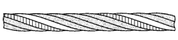
The invention relates to a laid rope (1a; 1b), in particular a laid wire rope, a laid fibre rope or a laid hybrid rope, which has multiple helically arranged outer strands (3a; 3b), which form an outer strand layer of the laid rope (1a; 1b), wherein each of the outer strands (3a; 3b) comprises multiple helically arranged outer strand wires (6a, 12; 6b, 12b, 17), wherein the outer strand wires (6a, 12; 6b, 12b, 17) are preferably arranged helically around an outer strand insert (5a; 5b). A length of the outer strand (3a; 3b) over a rope lay length LS is (n+z) times a lay length of the outer strand (3a; 3b), wherein n = 0, 1, 2, 3, 4, 5, 6, 7 and z= 0, ¼, ½, ⅓, ¾, and (n+z) > 0. The invention further relates to a device having a drum drive, to a device having a drive pulley, and to a belt.
SEOUL NATIONAL UNIVERSITY HOSPITAL (République de Corée)
DAEGU GYEONGBUK INSTITUTE OF SCIENCE AND TECHNOLOGY (République de Corée)
KOSWIRE LTD. (République de Corée)
Inventeur(s)
Yoon, Chang Hwan
Choi, Hong Soo
Hwang, Jun Sun
Park, Jae Geun
Abrégé
Disclosed is a micro-medical robot-based guidewire for vascular intervention. The guidewire includes: a core shaft; an outer coil surrounding an outer circumference of a distal portion of the core shaft; a tip end to which a front end of the core shaft and/or a front end of the outer coil is connected; an outer joining unit configured to connect a rear end of the outer coil and a rear end of the core shaft; an inner joining unit, disposed inside the outer coil, configured to connect the outer coil and an outer surface of the core shaft; and at least two magnetic bodies, disposed at a specific section in the inner space of the outer coil, wherein each of the magnetic bodies with each through-hole being formed at each center thereof is configured to allow the front end of the core shaft to go through said each through-hole.
1'2'2'), in particular a non-rotating round wire rope, which has a core cable (2) and outer wires (4) which surround the core cable, said outer wires forming a single outer wire layer (3). Advantageously, the core cable (2) comprises multiple core cable inner wires (5, 6) which are introduced into a plastic matrix (9) and which are surrounded by core cable outer wires (8) that form a core cable outer layer (7). Advantageously, a relative movement of the core cable wires can be carried out in the longitudinal direction as well as in the circumferential direction. The invention additionally relates to a method for producing a non-rotating wire rope and to a lifting device comprising a drum drive which has a non-rotating wire rope according to the invention, said wire rope being designed as a running cable.
Scherdel Innotec Forschungs- Und Entwicklungs- GmbH (Allemagne)
Inventeur(s)
Yu, Gwang Weon
Zaumseil, Wolf-Thilo
Guenthner, Martin
Abrégé
The disclosure relates to a steel wire and a spring having excellent antibacterial properties and corrosion resistance, and methods of manufacturing the same. The steel wire having excellent antibacterial properties and corrosion resistance includes: a steel wire; and a plating layer formed on the steel wire, wherein the plating layer includes a zinc (Zn)-aluminum (Al) plating layer plated on a surface of the steel wire, and a doping layer formed by doping a surface of the Zn—Al plating layer with a metal in a colloidal form. The method of manufacturing the steel wire having excellent antibacterial properties and corrosion resistance includes forming a plating layer on a surface of a steel wire, wherein the forming of the plating layer includes forming a Zn—Al plating layer by plating the surface of the steel wire, and forming a doping layer by doping a surface of the Zn—Al plating layer with a metal in a colloidal form.
B32B 15/01 - Produits stratifiés composés essentiellement de métal toutes les couches étant composées exclusivement de métal
C22C 18/04 - Alliages à base de zinc avec l'aluminium comme second constituant majeur
F16F 1/02 - Ressorts en acier ou faits d'un autre matériau ayant une faible friction intérieureRessorts enroulés, de torsion, à lame, en forme de coupelles, à corps annulaire ou similaire, le matériau de ressort ne jouant pas de rôle
5.
PLATED STEEL WIRE AND MANUFACTURING METHOD FOR THE SAME
HONGDUK INDUSTRIAL CO., LTD. (République de Corée)
Inventeur(s)
Kim, Tae-Chul
Kim, Jong-Sung
Kang, Sung-Hoon
Yu, Gwang-Weon
Sohn, Il-Ryoung
Kim, Jong-Sang
Abrégé
A plated steel wire, according to one aspect of the present invention, comprises: a base steel wire; and a zinc alloy plated layer. The zinc alloy plated layer comprises, in percentage by weight: 1.0% to 3.0% of AI; 1.0% to 2.0% of Mg; 0.5% to 5.0% of Fe; and the balance being Zn and unavoidable impurities, and includes a Zn/MgZn2/AI ternary eutectic structure, a Zn single-phase structure, and an Fe—Zn-AI-based crystal structure, wherein the Fe—Zn-AI-based crystal structure is formed adjacent to the base steel wire, and can have an average thickness of ⅕ to ½ with respect to an average thickness of the zinc alloy plated layer.
b) is beneficially made of a composite material having reinforcing fibers (12), the reinforcing fibers (12) of which composite material are laid to form at least one reinforcing line (11). Advantageously, a laid cable which is stable under transverse pressure is provided. The invention also relates to a strand, to a method for manufacturing a cable and a strand, to an apparatus for producing a cable and/or a strand, as well as an apparatus with a drum drive, said apparatus comprising a cable according to the invention.
SEOUL NATIONAL UNIVERSITY HOSPITAL (République de Corée)
DAEGU GYEONGBUK INSTITUTE OF SCIENCE AND TECHNOLOGY (République de Corée)
KOSWIRE LTD. (République de Corée)
Inventeur(s)
Yoon, Chang Hwan
Choi, Hong Soo
Hwang, Jun Sun
Park, Jae Geun
Abrégé
Disclosed is a micro-medical robot-based guidewire for vascular intervention, the guidewire being characterized by comprising: a core shaft; an outer coil wound around the outer circumference of a distal portion of the core shaft; a front end tip to which at least a portion of the front end of the distal portion of the core shaft and the front end of the outer coil are joined; an outer joint part that joins the rear end of the outer coil to the rear end of the distal portion of the core shaft; an inner joint part that is located inside the outer coil and formed so as to join the outer coil and the outer side of the core shaft between the front end tip and the outer joint part; and at least two magnetic bodies which have cavities formed therein and are located inside the outer coil in at least some sections between the front end tip and the inner joint part, wherein at least a portion of the front end of the core shaft positioned between the front end tip and the inner joint part passes through the cavities.
SCHERDEL INNOTEC FORSCHUNGS- UND ENTWICKLUNGS-GMBH (Allemagne)
Inventeur(s)
Yu, Gwang Weon
Zaumseil, Wolf-Thilo
Gunthner, Martin
Abrégé
The present invention relates to a steel wire and spring with excellent antibacterial properties and corrosion resistance and a method for manufacturing same. The steel wire with excellent antibacterial properties and corrosion resistance, according to the present invention, comprises: a steel wire; and a plating layer formed on the steel wire, wherein the plating layer includes: a Zn-Al plating layer plated on the surface of the steel wire; and a doping layer formed by doping a metal in a colloidal form on the surface of the Zn-Al plating layer. The method for manufacturing the steel wire with excellent antibacterial properties and corrosion resistance, according to the present invention, comprises a plating step of forming a plating layer on the surface of the steel wire, wherein the plating step comprises: a surface plating step of plating the surface of the steel wire to form a Zn-Al plating layer; and a doping step of doping a metal in a colloidal form on the surface of the Zn-Al plating layer to form a doping layer.
C23C 28/02 - Revêtements uniquement de matériaux métalliques
C23C 28/00 - Revêtement pour obtenir au moins deux couches superposées, soit par des procédés non prévus dans un seul des groupes principaux , soit par des combinaisons de procédés prévus dans les sous-classes et
C23C 18/16 - Revêtement chimique par décomposition soit de composés liquides, soit de solutions des composés constituant le revêtement, ne laissant pas de produits de réaction du matériau de la surface dans le revêtementDépôt par contact par réduction ou par substitution, p. ex. dépôt sans courant électrique
9.
Plated steel wire and manufacturing method for the same
HONGDUK INDUSTRIAL CO., LTD. (République de Corée)
Inventeur(s)
Kim, Tae-Chul
Kim, Jong-Sung
Kang, Sung-Hoon
Yu, Gwang-Weon
Sohn, Il-Ryoung
Kim, Jong-Sang
Abrégé
A plated steel wire, according to one aspect of the present invention, comprises: a base steel wire; and a zinc alloy plated layer. The zinc alloy plated layer comprises, in percentage by weight: 1.0% to 3.0% of Al; 1.0% to 2.0% of Mg; 0.5% to 5.0% of Fe; and the balance being Zn and unavoidable impurities, and includes a Zn/MgZn2/Al ternary eutectic structure, a Zn single-phase structure, and an Fe—Zn—Al-based crystal structure, wherein the Fe—Zn—Al-based crystal structure is formed adjacent to the base steel wire, and can have an average thickness of ⅕ to ½ with respect to an average thickness of the zinc alloy plated layer.
UNIVERSITY OF ULSAN FOUNDATION FOR INDUSTRY COOPERATION (République de Corée)
Inventeur(s)
Shin, Il Gyun
Lee, Sang-Soo
Abrégé
A fine needle and an endoscopic device are disclosed. From among these, the fine needle comprises: a hollow tube part of which at least a portion extends in one direction; at least one main blade part provided on one side of the tip of the tube part; and at least two sub blade parts provided on the other side of the tip of the tube part, wherein the main blade part can be formed so that the length thereof in one direction from the tip of the tube part is longer than that of the sub blade part.
HONGDUK INDUSTRIAL CO., LTD. (République de Corée)
Inventeur(s)
Kim, Tae-Chul
Kim, Jong-Sung
Kang, Sung-Hoon
Yu, Gwang-Weon
Sohn, Il-Ryoung
Kim, Jong-Sang
Abrégé
22/AI ternary eutectic structure, a Zn single-phase structure, and an Fe-Zn-AI-based crystal structure, wherein the Fe-Zn-AI-based crystal structure is formed adjacent to the base steel wire, and can have an average thickness of 1/5 to 1/2 with respect to an average thickness of the zinc alloy plated layer.
The present invention relates to a KINIZ alloy having a homogeneous microstructure. The KINIZ alloy comprises: combined wt% of copper (Cu) and iron (Fe) of 75-95 wt%, 1-20 wt% of nickel (Ni), 0.1-5.0 wt% of zirconium (Zr), and the remainder of inevitable impurities. The KINIZ alloy comprises: combined wt% of Cu and Fe of 75-95 wt%, 2.0-5.0 wt% of manganese (Mn), 0.3-1.0 wt% of Zr, and the remainder (excluding 0%) of inevitable impurities.
The present invention pertains to: an ultra-high strength aluminum cladding steel wire for overhead transmission lines; and a method for manufacturing same. The aluminum cladding steel wire is characterized by comprising: a steel wire containing 0.88-1.2 wt% of carbon (C), 0.1-1.5 wt% of silicon (Si), 0.3-0.7 wt% of manganese (Mn), 0.2-0.8 wt% of chromium (Cr), 0.001-0.02 wt% of phosphorous (P), 0.001-0.02 wt% of sulfur (S), and 0.001-0.3 wt% of copper (Cu), with the remainder comprising iron (Fe) and inevitable impurities; and an aluminum cladding layer formed by cladding aluminum on the steel wire after the steel wire has been primarily drawn, wherein the aluminum cladding steel wire having the aluminum cladding layer formed thereon is secondarily drawn to have a tensile strength of 190-240 kgf/m2 and a conductivity of 14-21% IACS. The method for manufacturing the ultra-high strength aluminum cladding steel wire for overhead transmission lines is characterized by comprising a steel wire preparation step, a primary drawing step, a cladding step, and a secondary drawing step.
B21C 37/04 - Fabrication de tôles, barres, fils, tubes ou profilés métalliques ou de produits semi-finis similaires, non prévue ailleursFabrication de tubes de forme particulière des barres ou fils métalliques
H01B 7/22 - Fils rubans ou métalliques, p. ex. d'acier
The present invention relates to a wire having etched grooves and a method for manufacturing same, the method enabling enhanced adhesion with rubber by means of forming a pattern of various depths and shapes on a wire plating layer by using a plasma apparatus. The wire, having etched grooves, comprises: a wire; and a plating layer plated on the wire, wherein the plating layer has etched grooves surface-etched by means of a plasma apparatus and having a pattern. The method for manufacturing the wire having etched grooves comprises: a wire preparing step; a plating step for plating wires and thus forming a plating layer; and a surface-etching step for surface-etching the plated wires, which have been formed by means of the plating step, by means of a plasma apparatus and thus forming etched grooves, which have a pattern, on the plating layer.
The present invention relates to a wire having etched grooves and a method for manufacturing same, the method enabling enhanced adhesion with rubber by means of forming a pattern of various depths and shapes on a plating layer of a stranded wire by using a plasma apparatus. The stranded wire, having etched grooves, comprises: a strand which is formed by means of stranding a plurality of wires; and a plating layer which is formed on the surface of the strand, wherein the plating layer has etched grooves surface-etched by means of a plasma apparatus and having a pattern. The method for manufacturing the stranded wire having etched grooves comprises: a wire preparing step; a plating step for plating wires and thus forming a plating layer; a stranding step for stranding the plurality of wires and thus forming a strand; and a surface-etching step for surface-etching the strand by means of a plasma apparatus and thus forming etched grooves, having a pattern, on the plating layer formed on the surface of the strand.
The present invention relates to a clad steel wire and a manufacturing method thereof, the method comprising: a first step of plasma-heat treating the surface of a steel wire; a second step of cladding the steel wire, having undergone the first step, with a clad member in a strip state; a third step of plasma-heat treating the clad steel wire having undergone the second step; a fourth step of hot rolling the clad steel wire, having undergone the third step, using a rolling roll; and a fifth step of wire drawing the clad steel wire, having undergone the fourth step, using a wire drawing machine. As such, it is possible to improve the bonding property between a steel wire and a clad member, thereby manufacturing a steel wire excellent in corrosion resistance.
B21C 37/04 - Fabrication de tôles, barres, fils, tubes ou profilés métalliques ou de produits semi-finis similaires, non prévue ailleursFabrication de tubes de forme particulière des barres ou fils métalliques
B23K 20/04 - Soudage non électrique par percussion ou par une autre forme de pression, avec ou sans chauffage, p. ex. revêtement ou placage au moyen d'un laminoir
D07B 1/06 - Cordes ou câbles de fils métalliques, p. ex. de fil métallique profilé autour d'un noyau de chanvre
D07B 5/00 - Fabrication de cordes ou câbles avec des matériaux spéciaux ou de forme particulière
Provided is an elevator wire rope in which fiber cores having a high grease content are arranged in an empty space between center strands and inner-layer strands or an empty space between the center strands to improve flexibility while maintaining properties such as high elasticity and low elongation. The wire rope includes: a rope core including center strands and fiber cores, each of the center strands being formed by twisting wires; inner-layer strands each formed by twisting wires, the inner-layer strands being arranged around the rope core; and outer-layer strands each formed by twisting wires, the outer-layer strands being arranged around the inner-layer strands. The inner-layer strands are ten in number, and the outer-layer strands are ten in number. The fiber cores are arranged in at least one of an empty space between the center strands and the inner-layer strands and an empty space between the center strands.
The present invention relates to a rope for an elevator. The rope for the elevator comprises: a center strand formed by twisting a plurality of wires; inner layer strands formed by twisting the plurality of wires and arranged along the outer periphery of the center strand; and outer layer strands formed by twisting the plurality of wires and arranged along the outer periphery of the inner layer strands, wherein ten of each of the inner layer strands and the outer layer strands are prepared, the diameter of the center strand, the diameter of the inner layer strand and the diameter of the outer layer strand are respectively 0.33-0.35 times, 0.13-0.15 times and 0.22-0.24 times as large as the diameter of a first imaginary circle circumscribed around the outer layer strands, and a fill factor is 64-67%.
The present invention relates to a wire for wrapping which is wound spirally on the outer circumference of a main cable in which a plurality of metal wires are compactly arranged in parallel, wherein the wire for wrapping is a zinc-aluminum-alloy-coated shaped steel wire with superior corrosion resistance which has an S-shaped cross section coated with a zinc-aluminum alloy and has a thickness of coating layer of at least 20 ㎛ at any part of the outer circumference of the S-shaped cross section. A method of producing a zinc-aluminum-alloy-coated shaped steel wire according to the present invention comprises the steps of: primarily rolling a material wire rod; performing stress-relief heat treatment for the primarily rolled wire at a temperature of 300-500℃; coating the heat-treated primarily rolled wire with a zinc-aluminum alloy; and secondarily rolling the coated primarily rolled wire at a rolling quantity of 5-40% to obtain the shaped steel wire of the S-shaped cross section.
B21B 1/16 - Méthodes de laminage ou laminoirs pour la fabrication des produits semi-finis de section pleine ou de profilésSéquence des opérations dans les trains de laminoirsInstallation d'une usine de laminage, p. ex. groupement de cagesSuccession des passes ou des alternances de passes pour laminer du fil métallique ou un matériau semblable de petite section
The present invention relates to a wire rope for a high-rise elevator. The wire rope according to the present invention comprises a center strand, which comprises 36 element wires, ten outer strands, each comprising 26 element wires, twisted around the center strand, and ten steel cores, each comprising seven element wires, interposed between the center strand and the outer stands, thereby defining a 10×26+[1×36+10×7] structure, wherein at least one of the steel cores comprises a fiber core (F) at the center thereof, thereby defining a 10×26+[{(10-N)×7+N×(6+F)}+1×36](N=1-10) structure. The present invention relates to a wire rope for a high-rise elevator, which maintains high-elasticity and low-elongation characteristics, and which guarantees stable inunction.
The present invention relates to a guitar wire, which is used for an electric guitar or an acoustic guitar, for example, wherein a brass plating layer, which has a copper content of 55-70% and a zinc content of 30-45%, is formed on the surface of a steel wire to have a thickness of 0.1-0.5μm, a molten tin plating layer is formed on the brass plating layer, and the total thickness of the brass plating layer and the molten tin plating layer is equal to or less than 5μm, thereby providing an excellent exterior quality and an improved plating adhesion. A method for manufacturing a steel wire for a spring according to the present invention comprises the steps of: primarily dry-drawing a material wire rod such that the same has a diameter of 2.0-4.0mm; heat-treating the primarily drawn steel wire and then secondarily dry-drawing the same such that the same has a diameter of 0.5-2.5mm; forming a brass plating layer on the surface of the secondarily drawn steel wire; tertiarily drawing the same such that the final wire diameter is 0.1-1.1mm, and the brass plating layer has a thickness of 0.1-0.5μm; and passing the tertiarily drawn steel wire through a molten tin plating bath such that a molten tin plating layer is formed thereon.
C23C 2/04 - Procédés de trempage à chaud ou d'immersion pour appliquer le matériau de revêtement à l'état fondu sans modifier la forme de l'objet immergéAppareils à cet effet caractérisé par le matériau de revêtement
C23C 2/28 - Post-traitement thermique, p. ex. par traitement dans un bain d'huile
The present invention relates to a rope for an elevator. The rope for the elevator comprises: a center strand formed by twisting a plurality of wires; inner layer strands formed by twisting the plurality of wires and arranged along the outer periphery of the center strand; and outer layer strands formed by twisting the plurality of wires and arranged along the outer periphery of the inner layer strands, wherein ten of each of the inner layer strands and the outer layer strands are prepared, the diameter of the center strand, the diameter of the inner layer strand and the diameter of the outer layer strand are respectively 0.33-0.35 times, 0.13-0.15 times and 0.22-0.24 times as large as the diameter of a first imaginary circle circumscribed around the outer layer strands, and a fill factor is 64-67%.
According to the present invention, a coated steel stranded cable comprises a plurality of strands, and one central strand, and a plurality of lateral strands stranded on an outside of the central strand. The central strand and the plurality of strands include, in weight %: 0.9~1.2% of C, 0.4~0.7% of Mn, 1.0~1.5% of Si, 0.4~0.7% of Cr, less than 0.01% of P, less than 0.01% of S, and a residual amount of Fe and other inevitable impurities.
Provided is a nickel (Ni)-copper (Cu) plated high-carbon steel wire for springs. The Ni-Cu plated high-carbon steel wire includes a core wire that includes a high-carbon steel wire; and a Ni-plating layer and a Cu player which are sequentially plated on a surface of the core wire and then are drawn.
An object of the invention is to provide a high strength and light hybrid rope. At the center of the hybrid rope 1, there is arranged a high strength synthetic fiber rope 3 formed by braiding multiple high strength synthetic fiber bundles 30 each composed of multiple high strength synthetic fiber filaments 31. Given that the pitch of braid of the high strength synthetic fiber bundles 30 is represented by “L” and the diameter of the high strength synthetic fiber rope 3 is represented by “d”, the pitch of braid “L” and the diameter “d” are adjusted such that the value L/d is equal to or higher than 6.7.
Disclosed is a hybrid rope which has enhanced strength and a reduced weight. The hybrid rope (1) includes, disposed in the center thereof, a high-strength synthetic-fiber rope (3) formed by braiding a plurality of high-strength synthetic-fiber bundles (30) each composed of a plurality of high-strength synthetic fiber filaments (31). The braiding pitch L of the high-strength synthetic-fiber bundles (30) and the diameter d of the high-strength synthetic-fiber rope (3) have been regulated so that the value of L/d is 6.7 or more.
D07B 1/04 - Cordes faites de matériaux fibreux ou filamenteux, p. ex. d'origine végétale ou animale, de cellulose régénérée, de matière plastique avec une âme de fibres ou filaments disposés parallèlement à la ligne centrale
D07B 1/16 - Cordes ou câbles avec gaine enveloppante ou incrustations en caoutchouc ou matière plastique